
Henrik Fidje
Member of suspension department
Managing: In-Wheel
The upright assembly has many functions within the wheel assembly. It houses the wheel hub, which allows for connection and rotation of the wheels. The brake calipers are mounted to the upright. Steering mounts allows for steering of the wheels in the front and toe control in the rear. It also connects the double wishbones to the outboard assembly and transfers the forces from the tire contact patch to the suspension links. In addition to all these functions, which allow for safe and functional handling of the car, there are also some structural conditions that are important to take into account when designing an upright.
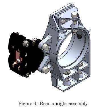
The suspension system is not a static system, as everything is elastic to some extent (compliance). There are large forces that are transferred through many components in the inwheel assembly. These forces will cause compliance which will affect the chosen suspension geometry and, in most cases, reduce handling. Figure 3 and Figure 4 shows both the front and rear upright assembly.
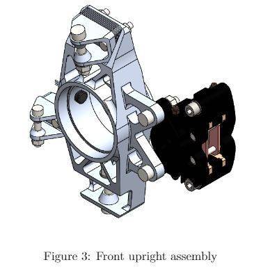
Front upright assembly
One of the main focuses for this year compared to last year is to reduce weight, generate better load paths and improve the workability of the attached components. In addition to this, a wheel speed concept, that was partially integrated last year, has been fully implemented to the upright assembly.
Adjustability has also been an important factor in the 2020 design. Because of some unseen challenges, many variables in the suspension geometry has not been sufficiently simulated. Therefore, adjustability has been important to ensure that during the test phase of the vehicle the best possible camber and steering geometry can be found. This will also provide valuable data for teams in the future, as fewer changes will be made in the suspension.
To adjust the camber angle, shims with variable thicknesses are mounted with the upper wishbone bracket, as shown in \Figure 3. This allows us to adjust the camber angle up to 3.5 degrees. In the front tie-rod attachment, a double shear clevis attachment is mounted. The reason for this clevis attachment is the possibility for adjustment if the steering geometry is not adequate. From simulations and calculations, there will most likely not be any problems. In addition, this will allow for a much simpler machining job, as it can be done quite simply with a 3-axis CNC mill.
All spacers are made conical to both reduce the pressure acting on the upright and brackets and allow for more radial rotation of the uniball bearings.
Cuts in the lower wishbone mount have also been made, to ensure that the wishbones do not touch the upright under operation. In the previous years, this was honed manually, which was a time-consuming task.
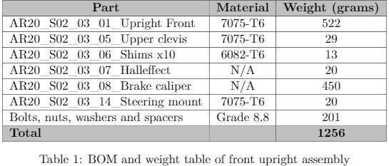
Table 1 shows a BOM and weight table for the front upright assembly. From last year, the front hub size has decreased significantly, which has made it possible to reduce the weight of the front upright by 21 %. Comparing last years upright with the current design, there has been a significant increase in stiffness. This is due to better load paths and a better understanding of where the critical areas are.
Rear upright assembly
The same focus has been made under the construction of the rear upright, as with the front upright. The size of the bore of the upright is the same as last year, to accommodate for the in-hub tripod joint, which has shown to be a very successful concept. One other major change is the tie-rod attachment. Last year the team tried to use bumpsteer to their advantage and allow for some rear-wheel steering. This concept was proved not to be successful. For the 2020 season, the team tried to reduce bumpsteer in the rear to a minimum, as rear toe-control is far more important.
To reduce the rear bumpsteer, the tie-rod attachment is in-plane with the lower wishbone attachment. The tie-rod attachment on the rear bulkhead is also attached at the same point. This will, in theory, result in no bumpsteer at all.
There has also been a focus on camber adjustment in the rear with shims. These shims will also have a variable thickness so that the team can evaluate the best camber settings for competition.
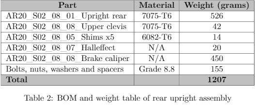
Table 2 shows a BOM and weight table of the rear upright assembly. The weight of the upright has improved by about 20 % from last year, even though the bore size of the hub has stayed the same. There has also been a significant improvement in the compliance in the rear tie-rod attachment.
Rules
Relevant rules for the inwheel assembly:
- T 2.3.1 – The vehicle must be equipped with fully operational front and rear suspension systems including shock absorbers and a usable wheel travel of at least 50 mm and a minimum jounce of 25 mm with driver seated.
- T 2.4.1 – Any wheel mounting system that uses a single retaining nut must incorporate a device to prevent loosening of the nut and the wheel. A second nut (“jam nut”) does not meet these requirements.
- T 2.4.2 Standard wheel lug bolts and studs must be made of steel and are considered engineering fasteners. Teams using modified lug bolts, studs or custom designs will be required to provide proof that good engineering practices have been followed in their design. Wheel lug bolts and studs must not be hollow.
- T 2.4.3 – Aluminum wheel nuts may be used, but they must be hard anodized and in pristine condition.
- T 2.6.3 – The steering system must have positive steering stops that prevent the steering linkages from locking up. The stops must be placed on the rack and must prevent the tires and rims from contacting any other parts. Steering actuation must be possible during standstill.
- T 10.1.1 – Critical fasteners are defined as bolts, nuts, and other fasteners utilized in the primary structure, the steering, braking, driver’s harness, suspension systems and those specifically designated as critical fasteners in the respective rule.
- T 10.1.2 – All threaded critical fasteners must be at least of either 4 mm in diameter or of the diameter specified in the referencing rule, whichever is larger.
- T 10.1.3 – All threaded critical fasteners must meet or exceed metric grade 8.8 or equivalent.
- T 10.1.4 – All threaded critical fasteners must be of the type hexagon bolts (ISO 4017, ISO 4014) or socket head cap screws (ISO 4762, DIN 7984, ISO 7379) including their fine-pitch thread versions. Alternative fasteners are permitted if the team can show equivalence.
- T 10.1.5 – Bolts may be shortened in length as long as T 10.2.3 is fulfilled.
- T 10.2.1 – All critical fasteners must be secured from unintentional loosening by the use of positive locking mechanisms.
- T 10.2.2 The following methods are accepted as positive locking mechanisms:
- Correctly installed safety wiring.
- Cotter pins.
- Nylon lock nuts (ISO 7040, ISO 10512, EN 1663 or equivalent) for low temperature locations (80 ◦C or less).
- Prevailing torque lock nuts (DIN 980, ISO 7042 or equivalent, and jet nuts or K-nuts).
- Locking plates.
- Tab washers.
- Any locking mechanism based on pre-tensioning or an adhesive is not considered a positive locking mechanism.
- T 10.2.3 – A minimum of two full threads must project from any lock nut.
- T 10.2.4 – All spherical rod ends and spherical bearings on the steering or suspension must be in double shear or captured by having a screw/bolt head or washer with an outer diameter that is larger than the spherical bearing housing inner diameter.