Martin Hermansen
Member of Aero department
Managing: Undertray
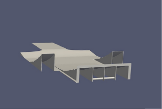
This is the first undertray designed and manufactured by Align Racing.
Concept
Since this was our, and Aligns, first time designing an undertray we learned that there are a lot of elements to consider. We started out with the following concepts:
Vortex generators
Vortex generators are primarily used to keep the flow attached, they can also be used as barriers to prevent flow entering the low-pressure zone under the vehicle. If air enters the low-pressure zone turbulence increases which leads to increased pressure. However, it may be an advantage to have vortices rolling up the diffuser to prevent the flow from separating. If vortex generators are low cost, easy to produce and implement, we should consider it.
However, the need for simulations with and without VGs are necessary to come to a conclusion.
Attachment method
We felt we had to think about this because we pherhaps could find a genius way to mount it. We talked about it for some time, but no one came up with any other good options but the obvious one.
Brackets and bolts.
Mould production method
On this concept 3 options are considered: Machined mould, Homemade mould and Homemade foam profiles. Firts comparing the weights of the options, two of the options stand out. Both moulds would be lighter than the homemade foam profiles. Regardig price, the first options is the worst. It is really expensive to order a machined mould from a professional manufacturer. The two other options scores higher on this point, beacuse manufacturing in house is consideribly cheaper. However. The in house capabilities are low and time consuming, in addition the quality will be lower. This will impact perfomance on the finished product.
Since perfomance is crucial, a machined mould would serve as the best option for our case. If we in early stages get a contract with a manufacturer, it is likely that the prices will be manageable.
Number of undertray channels
One could say this is a design phase concept. But it was chosen to write a report of it because the different solutions creates different problems for other groups. Since this is going to be the first year with focus on aerodynamics we think that it’s important that we get a positive effect on the vehicle, that helps to improve the overall result of the car. Because of this we are thinking to go with the option that we think is the most doable at the moment. Therefore we need an option that we can fit and mount on the car w/o extremly much trouble. And the option has to have space so we can change the profile of the diffuser if we have to. Could be because of the simulations doesn’t give the results we want.
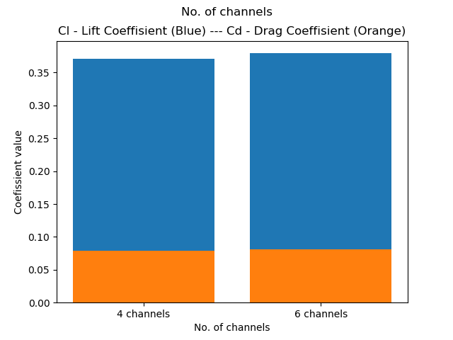
We are going for option because we think that we can get the most performance from this option this year. Wich is one channel is the middle that splits.
* In the design phase where a lot of CFD testing were done. This was changed to six channels due to performance and being able to jack up the vehicle.
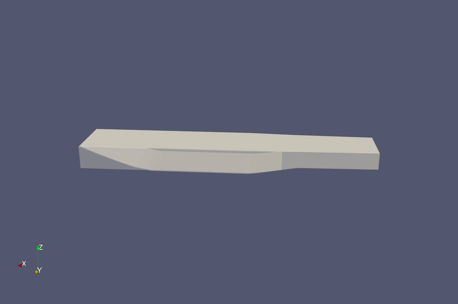
Design
The way the design of the undertray was attacked, was by isolating the most important factors that affects for downforce and drag, then tuning those to deliver the best results individually. The factors chosen was diffuser angle, flanges, jackingbar, skirt, smallest and largest area ratio, length, width, and strakes. When feeling confident with a result in CFD testing, the factor was locked in the SW-drawing. By continuously doing this the undertray started of looking quite “naked” until every factor was CFD tested and locked.
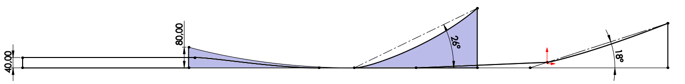
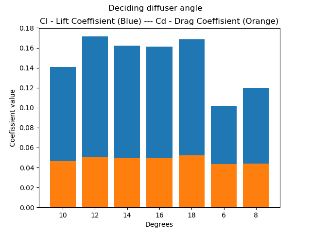
Diffuser angle (18 degrees): On the diffuser angle we did alot of testing, one should try to stick between 17-21 degrees.
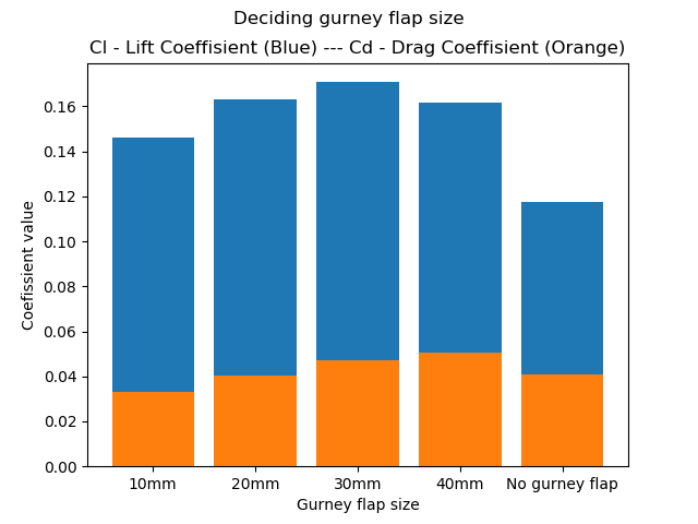
Gurney flap (30mm): The analysis showed us that around 30mm of gurney flap is good.
Jackingbar: One should try to avoid jackingbar inside diffuser at all cost! Destroys much of the diffusers purpose.
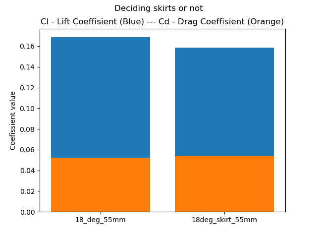
Skirt: Along the edge of the undertay one can have a “skirt”, this is used to force the air to stay underneath the car, and don’t exit out on the sides before reaching the diffuser. Due to our allready low ride heigth and a no-go on touching the ground in race, we found that it was not worth.
Smallest and largest area ratio (4-5): This ratio is pretty important, and is written alot about in different aerodynamic books. If one makes two rectangles from the ground up to the diffuser. Where one is at the begining and the other one in the end of the diffuser, these should have a ratio between 4-5. The rear rectangle should be 4-5 times larger than the one at the start of the diffuser. In our case we can just measure the heigth because the width stays the same.
Length: The longer your diffuser are, the steeper your diffuser angle can be.
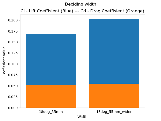
Width: The wider the undertray is, the larger surface area you get underneath the car. Then the “sucking force”, based on Bernoulli’s principle, has a larger area to work on. So one should try to have as wide undertray as possible.
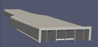
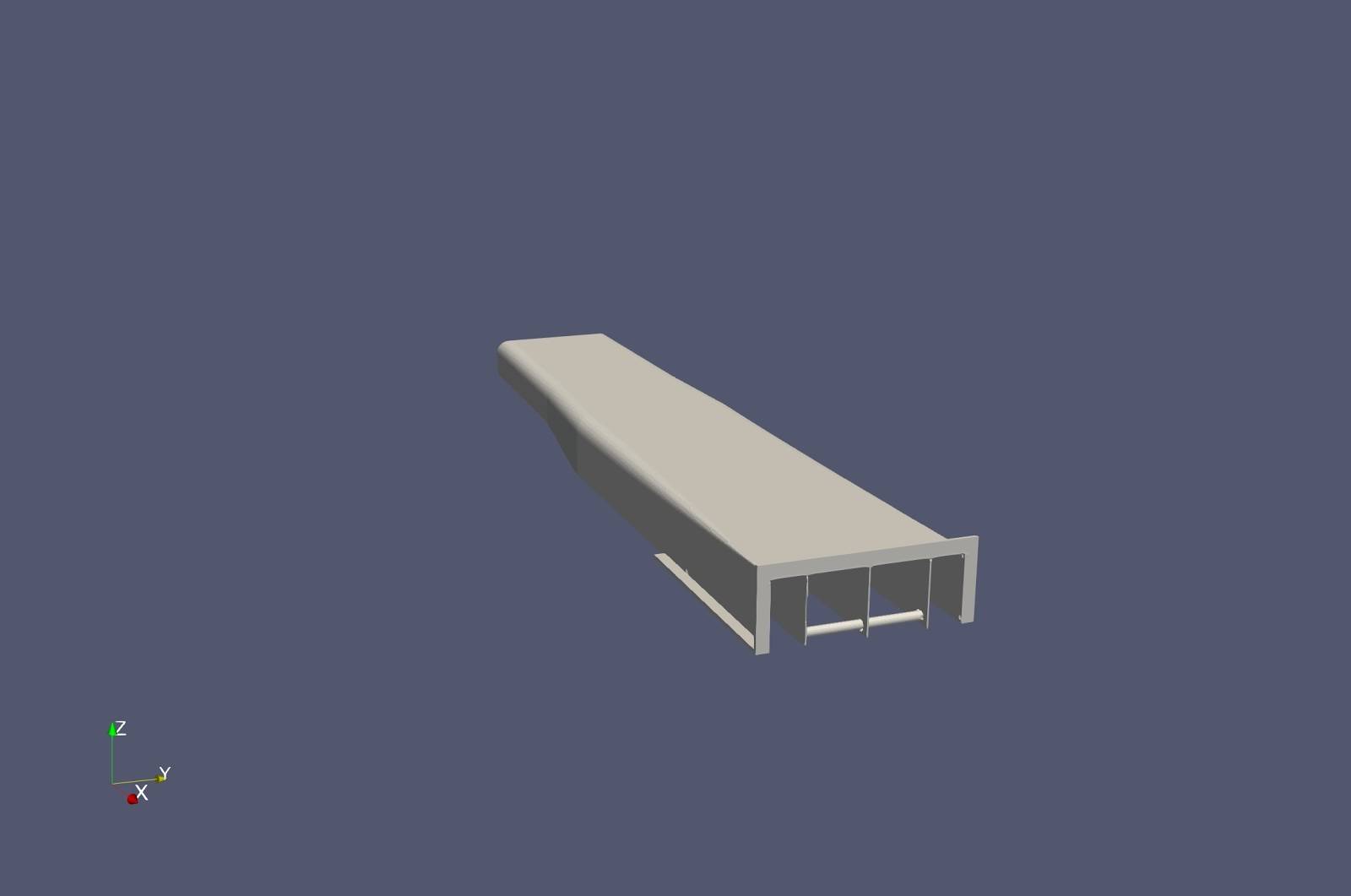
Strakes (5): Decided to go with 5 strakes because then these would be strong enough to jack up the car. The effect this has on the downforce and drag is minimal.
* Whats wrong by doing this is that the factors affect eachother. Since there was nothing to go on from previous years, this sacrifice was made.
CFD
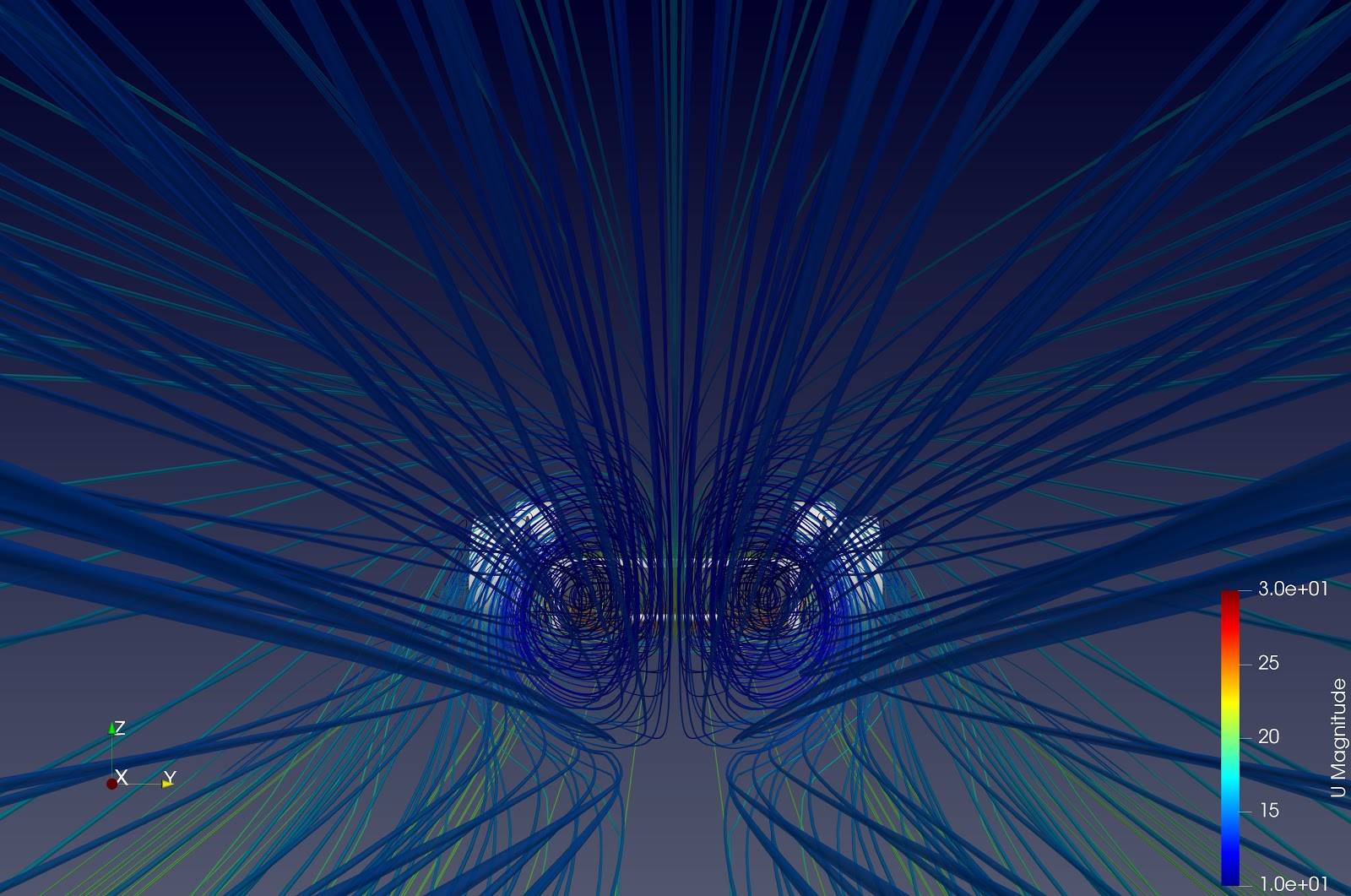
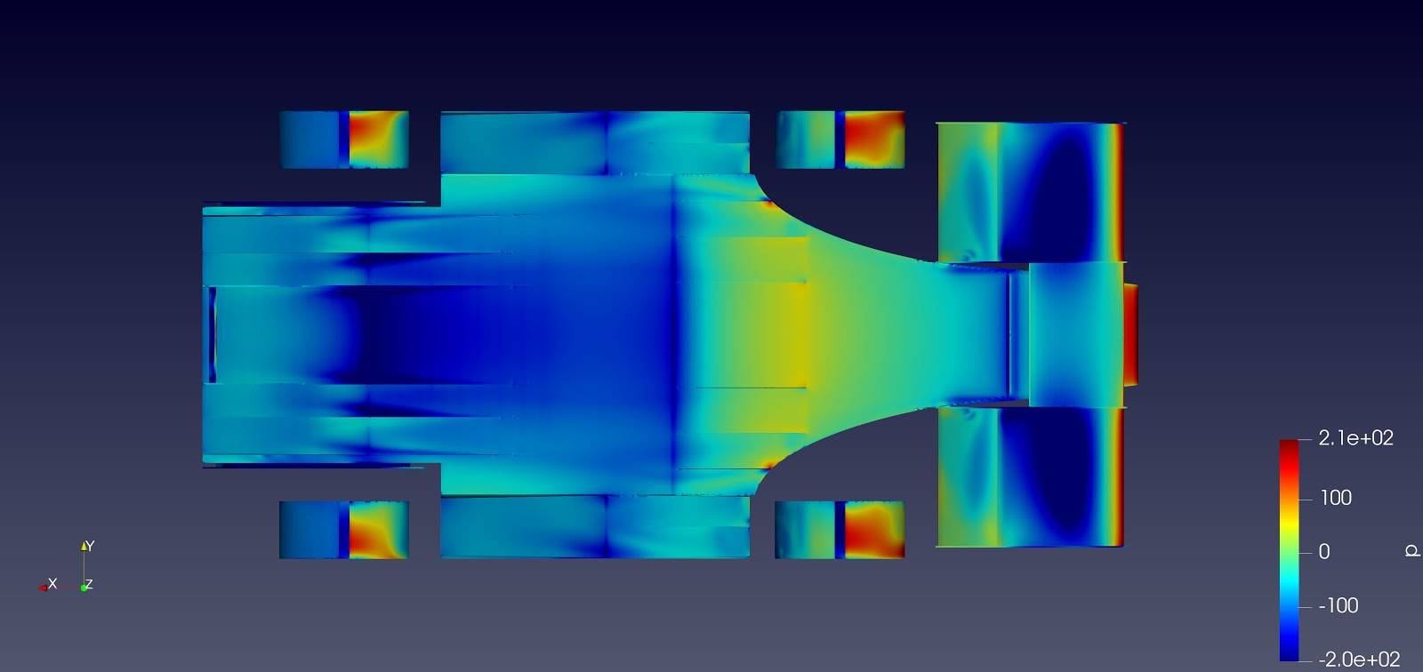
* All CFD-analysis of the same factor was done with the same boundrary values, but we changed them for testing between each factor. Therefore one can compare values of each factor, but not values from factor to factor.
Diffuser angle (18 degrees):
Gurney flap (30mm):
Jackingbar:

Skirt:
Width:
Strakes (5):
Smallest and largets area ratio (4-5): N/A
Length: N/A
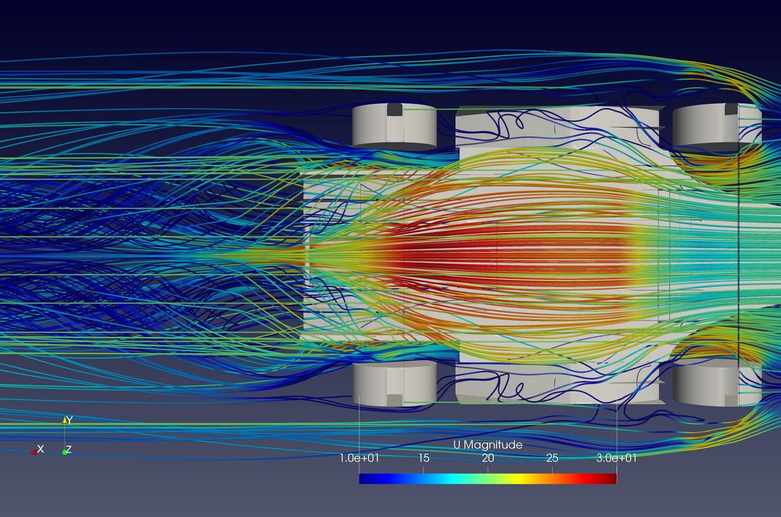
Airflow
Pressure
Production
Undertray (AR20_A04_01)
The undertray
Since we aren’t finished yet due to COVID-19 we can’t quite tell if the production method will be going to plan. But the plan is to honeycomb two thin carbon fiber undertray parts together, this will add stiffness and still keep the weigth low. This has been a succses in testing, and with the production of the strakes and endplates.
Gurney flaps:
The gurney flaps are made out of carbon fiber sheets. After we cut them in the appropriate measurements we firstly glued them onto they undertray, then we used a method called wet-layup to cast the gurney flaps and undertray together.
Strakes:
The production of the strakes started by laser cutting a piece of plexiglass to have an exact model of the strakes. Then we casted some thin sheets of carbon fiber and “honeycombed” these to increase the stiffness, but at the same time keeping the weigth to a minimum. Later they were cut with the help of the plexiglass model to be correct size. Now there were five strakes that needed a bit of sanding before we casted them into the undertray with the same method used with the gurney flaps. However we had to use a mockup we made out of wood to make sure they were casted into the exactly rigth location.
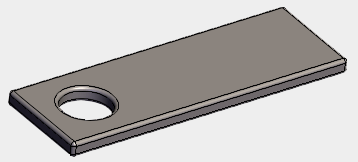
Rectangular brackets (AR20_A04_02)
Made by hand out of steel. Welded on.
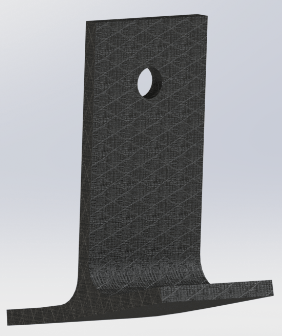
T-brackets (AR20_A04_03)
The T-brackets are made of carbon. We milled a mold of the bottom half out of polyurethane, then casted those into carbon. When we had the bottom half in carbon, we casted some thiccccc carbon plates perpendicular onto the bottom half. After this, we had the T-brackets. But we wanted to be sure that they were strong enough, therefore we wrapped the hole bracket in carbon once more and did a wet layup. Then we had the complete brackets.