
Christian Salem
Member of Electronics department
Managing: Power Electronics
Power Distribution Module [PDM]
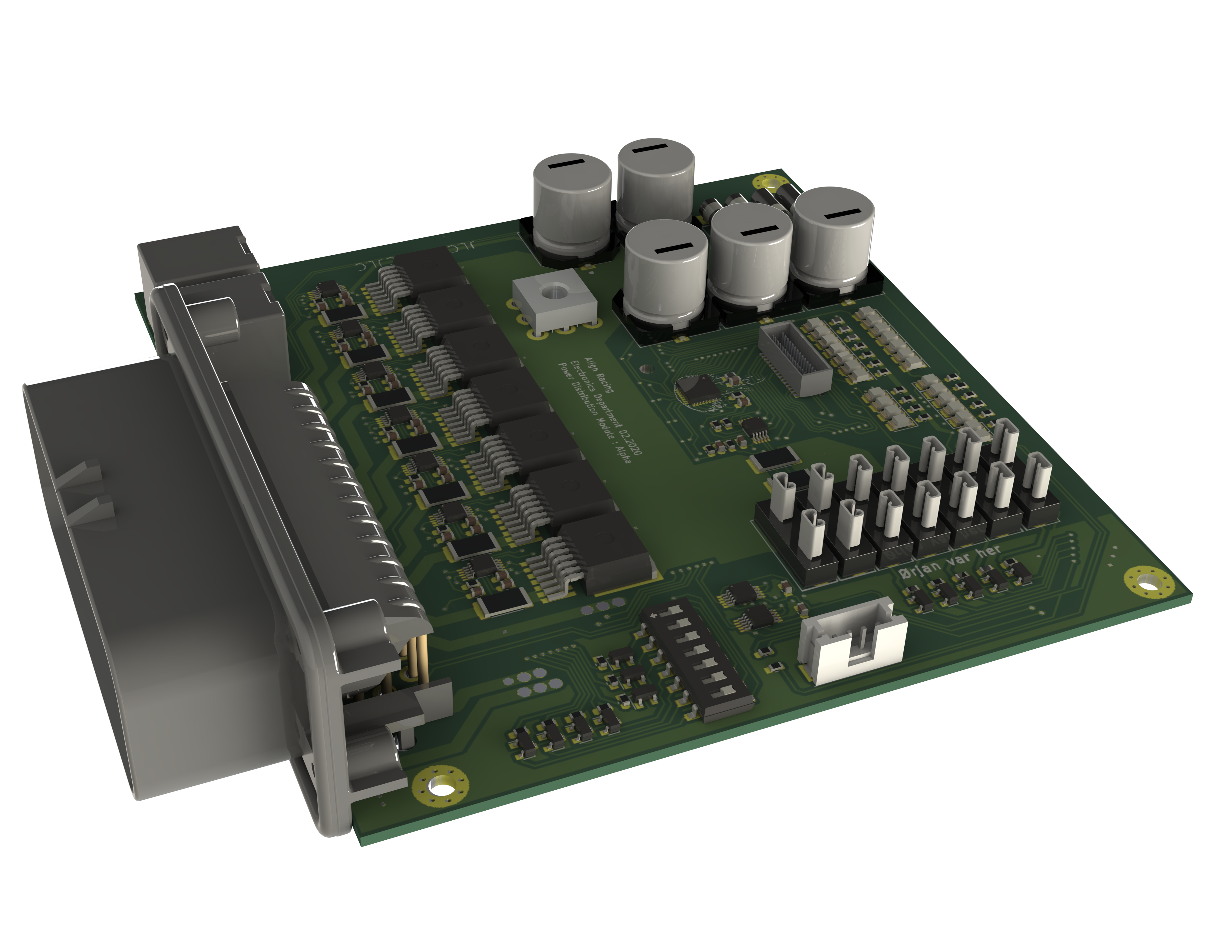
| Max total current: | 80 A |
|---|---|
| Max phase current: | 15 A |
| Phase count | 7 Fused Direct 7 Fully Digital 2 Shutdown Circuit Relays |
| Price Approx | 1500 Kr |
| Approximate weight | Guess: below 1 KG |
Why a pdm solution ?
PDM- power management module. Is a module where power is routed, switched, monitored, and more. Traditionally this is done by having separate fuses and relays connected together with traditional wires. And then controlled by a a separate controllers via signal wires. This is not space efficient and heavy. This is due to all components having individual cases, and a separate mounting hardware. In addition all connectors, cables, and cable management makes a big impact on space usage and weight. By integrating it all onto a Printed circuit board, we can considerably reduce the size and weight.
Every component looses its own mounting hardware and connector, and all of the bulky wiring is replaced with copper traces.
Components such as relays, and fuses is often available in circuit-board packages, often much smaller than standalone counterparts.
A PDM may switch or/and control many of a cars electrical systems. For example, fans, pumps, lights, actuators. Removing the need for separate controllers.
A such solution opens up a lot of opportunities. There is lot of technology available that can be integrated on a PCB, making for a future-oriented solution
Mechanical vs solid state components.
A pdm can be made purely mechanical. Meaning it consist of electro-magnetic relays, and traditional wire fuses. This type of pdm is predicted to be cheep, and easy to manufacture. This is also our backup plan. If we fail to develop a solid state PDM, it would be easy to fall back to this design.
In contrast, mosfets instad of relays, in combination with electronic fuses. This makes the system considerably smaller and lighter. In adition mosfet switching opens up possibility for PWM control, and advanced monitoring. However this is predicted to be lot harder to develop, and have a higher development cost. This is the solution we aim to develop this year.
Requirements , and a brief explanation:
PS: This applies only to the solid state pdm. If we fall back to our backup plan, none of this is valid. If we fall back to our backup plan, the only thing valid, would be to get a working, reliable car with traditional relays, and fuses, as discussed in “Mechanical VS solid state” paragraph.
This is a brief explanation, not a in depth reasoning. Please read the full technical documentation of the PDM, to fully understand, and to get the whole reason behind each choise.
– High Side Current Fusing and Switching. Any overcurent protection switch, needs to be placed highs side, in order to protect the whole system.
In addition, grounding can be done to frame, or directly to battery, instad back to PDM, saving a lot of weight in wires. This is how all professional PDM works.
– selectable amperage fuse / Over Current Protection.
Of Course we should be able to change the fuse value. Our PDM is designed flexible to allow multiple configurations, the fuse should be able to change values.
– Latching upon error, resetteble by a switch or eqv. (Applies to electronic fuses only)
Like any good fuse, our electronic fuses should be able to latch upon error, without it automatically reactivating into a short circuit. Automatic reactivation is sometimes desireble so we do not exclude this. However we should at least be able to latch it, if we would desire it. In fact, our current configuration of electronic fuses support both. Also we need some convinient method of resetting the fault.
– Switch or eqv. that turns off a particular circuit (Applies to electronic fuses only)
For troubleshooting purposes we should be able to deactivate a particular Phase/Circuit.
Same as removing a fuse in a regular setup.
– Indicator for fuse tripped/fuse deactivated
As it is impossible to tell whether an electronic fuse is tripped, just by looking at it, we need some sort of indicator to tell us.
Also we would like to know if a regular fuse is blown, just at a glance, without needing to disassemble the PDM.
Also in this case, we need some sort of indicator to tell us.
– Over current protection (OCP) done in components, not software. We have bent this rule! let me explain:
This is because of safety. At this moment, we think that programming reliably is a challenge. As OCP is one of the most important features, that prevents our car from catching on fire. Programming this feature is unneeded added complication, and a security risk. How ever we changed our mind a little.
Currently the OCP (Over Current Protection), it is done by a special IC chip. It triggers OCP without any help from a microprocessor, or any programming. However, it needs to be configured, every time the PDM is powered on. This configuration is done in software, violating this requirement somewhat. It is done so, because the chip we use makes for a small and neat PDM, has many nice features, and is generally future proof. Alltho somewhat complicated, we think that configuring it in software would be reliable enough, and that the most important and critcall part is still done in hardware. Read more about this in “Protection Section of the PDM”
– Externally controlled, without needing to program the I/O.
We would like to be able to control all the phases/Circuits of the PDM, externaly with simple signal wires (Aux Input). This is for redundancy, in case one of the systems fails, we have additional method of getting the car running. In addition if we fail to implement some of the systems in software or via can bus, there is always a backup method. A simple signal wire. For example : If we could not get the cooling system running via CAN bus, we could connect the PDM directly to ECU and switch it via a traditional signal wire. As of now, this is implemented. The program still handles configuration of the Over Current Protection, and thus needs to activate each input. This happens automatically upon initialization, and from then on, the aux inputs can be used, without any programming.
– Monitoring, and feedback, if possible.As monitoring is one of the advantages of having a fancy PDM, this is a kinda of a requirement. alltho if it proves to be a challange, we would not implement it. So its not really a requirement, but kind of. It still better to take a step further into the PDM technology, even tho without the monitoring, than omitting the PDM consept, just because lack of monitoring features.
Current Status:
Under development:
– Mosfets works like a charm, as well as i2C circuit.
– Need to test the fix for where AUX inputs was malfunctioning, on our newest PCB board. This fix is simulated in LT-Spice to work.
– Issue: where induced voltage is frying our monitoring chip. Solution: Add three resistors per monitoring chip to limit the current. Not yet tested.
Next is to test this solution, and incorporate it into the system.