
Henry Jensen
Member of Aero department
Managing: Rare-wing
Rear wing is an aerodynamic device mounted at the rear of a car. The job of the rear wing is mainly to get the most possible force against the ground (downforce), with the least possible force towards the direction of travel (drag). This is the first year we implement this kind of device on our car. Therefore our main focus has been to get the foundation for this type of development.
Concept
- Wing/No wing:
- Wing: The reasons for producing and using a rear wing are mainly performance gains, and marketing advantages. These reasons are higly weighted, as they play a vital role in our performance this year and the years to come.
- No wing: If budget is too tight, wings could be postponed until next year or the year after. As wings probably will be implemented soon anyway, we believe it should be done as early as possible, and if the budget will allow it, we have the knowledge and motivation to do so this year.
- Conclusion: Decided to go for wings, both rear and front. It gives better lap times, more design presentation points, more attractive to sponsors, better feeling of accomplishment for the whole team, as the car will look quite different to last year, and presumably quite spectacular.
- Wing production:
- Hollow: A hollow airfoil can be produced by pouring a chemical (acetone) into an already produced foam airfoil. The result is therefore a little more expensive and requires a little more work. In scenarios far above the CG, such as rear wing, a hollow airfoil will be preffered. An Icelandic team has a good production list on how-to produce hollow wings.
- Styrofoam: Styrofoam can be a solution if the budget gets very tight. I can possibly produce desired downforce, but amount of lost performance still unclear.
- High-quality foam: Compared to styrofoam, high-quality foam has a higher quality, and is therefore a bit more expensive. It is cheap to buy in large quantities, and will give us the training requred to master the techniqe and skills required to produce acceptable quality airfoils.
- Conclusion: A hollow airfoil can be used on the rear wing, due to low chance of impact damage and due to CG of the car. This is a much cheaper and lighter option then foam. These are early thoughts, and further research and analysis may alter the conclusion. (e.g. weight of hollow airfoil vs weight of foam-core airfoil with similar strength. It may prove beneficial to use foam core also for the rear wing). Decided to go for foam inside the wing. Not the most optimal option, but a safe option.
- Wing attachment method:
- The wings at the front and the back must be rigidly attached, unless one has to experiment with floating wings. Metal or carbon brackets are most commonly used in FSAE, which is perhaps the best way to attach the wings to get it completely rigid. Rods and wires are most commonly used to support when distances are too large to use a bracket. Attaching the aeropack directly to the frame or body is, by little research, not much used. This method requires a lot of planning in the design phase, and this years this time was rather spent on getting a airfoil design that could work.
- Conclusion: Therefore it was decided to go for aluminium brackets as the main bracket and some additional support such as carbon tubes and wires.
- Wing assambly method:
- Insert on the outside of the airfoil: This option has an edge/flange that rests on the wing profile. This can destroy the air flow that comes over the wing, but this is, at this stage, very early to say. Potentially, this may not be a problem. This is just as easy and cheap as the option with the insert inside. However, this option can be easier to replace, as well as being very easy to manufacture. You can, if you find that these can be 3D printed, create new ones right up to the competition. You don’t have to do much with the foam (it can be bought / made and molded to finished length). Maybe it can just be laid on the outside without being glued? It can also “hide” nastly edges from both side of the carbon/foam mold.
- Insert on the inside of the airfoil: This is a very clean alternative. It does not ruin the air flow, as well as being very light. The problem with this option is that it can be difficult to produce. Not the insert itself, but putting the insert in place. This requires work to design, making production simple. In addition, it can be challenging if you want to replace the insert or change the attachment points.
- Carbon reinforcement: This is a very smart option, where you just mold carbon reinforcements on the wing profile and glue the insert. This is very simple and inexpensive, but maybe the ugly edges on either side, which give height differences, can be a problem. Here you also trust that the glue and foams can withstand the loads that arise. This option also requires a lot of work shown to change the attachment point. Then you could potentially end up having to re-create the entire wing profile.
- Conclusion: It were decided to go for inserts inside of the airfoil. Aluminium brackets that were glued on both sides after the wing was finished casted.
- 2D airfoils:
- Conclusion: All same profile and flat endplates because easy to design, cost effective, easy to manufacture and with high chance of similarity between design and product.
Design
CFD/Airfoil selection
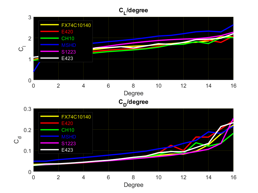
- 2D CFD of airfoil types at different angles(0-16 degrees) to decide which to use, together with ease of manufacture (thickness of trailing edge). Decided E423 for all profiles. The different results for the different types is shown in the graph below. The reason for not to choose MSHD or S1223 is the difficult production because of thin edges.
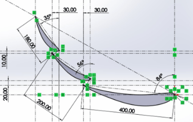
- Decided to go for 3 airfoils from the beginning. Most of the teams race with 3 airfoils and the CFD supervisor also recommended 3 airfoils. Also the chord length was set to 180, 200 and 400mm to minimize the number of variables in the flow simulation. Then 2D CFD of different concepts of airfoil positions(Angles, overlap and gap). The final results is shown in the picture below.
- Some tests were done this year about the endplate design also, but the results were not so accurate. Gurney flaps, sideflaps(vortex), extra airfoil and airfoil outside of the endplates was simulated. All gave better results, espesially gurney flaps and sideflaps, but was left out because of the uncertainty surrounding the need to firstly make something and then add stuff.
Production
Airfoils(AR20_A03_01)
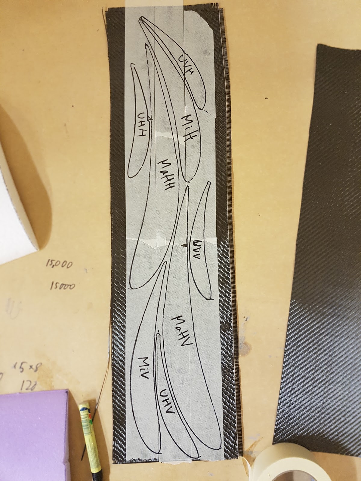
- Started with pre-cut airfoil profiles in foam.
- Glued the airfoils together with araldite (black) glue. Used toothpicks to prevent the parts from slipping apart.
- Cut the wings to finished length.
- Fold a layer of thin carbon fiber around the airfoil profile with spray glue.
- Cut out airfoil profiles in carbon fiber and glued on each side (tape worked really well to hold the carbon fibers in place).
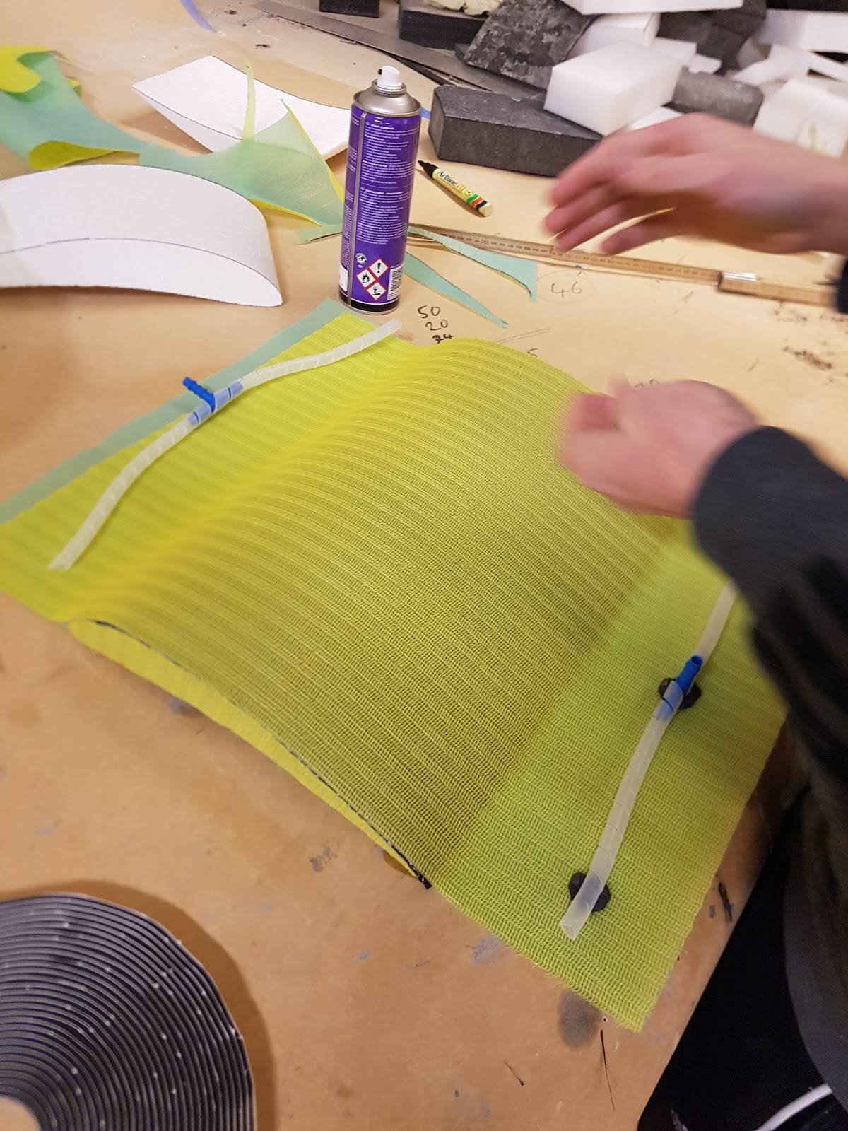
- A layer of spreading cloth under and over the wing profile in a kind of sandwich. It is important here to place the end of the
cloth outside the wing, or there will be bad marks in the wing from the spiral tubes.
- Cut out airfoil profiles of the spreading cloth and glued on each side (here no tape is needed to keep the cloth intact).
- Spiral tubes on the airfoil just outside the trailing and leading edge.
- Packed the airfoil in a plastic bag. Important to have a lot of plastic, especially on the sides.
- Pulled the epoxy from leading to trailing edge.
- Main flap weight 870 gram after the cast.
- Flap 1 weight 390 gram after the cast.
- Flap 2 weight 270 gram after the cast.
- Carefully sanded the sides on Flap 1 and 2 to prepare for gluing.
- Glued both airfoil brackets(AR20_A03_03/04) to each flaps and screwed some screws through a wood plate and in to the carbon airfoil to hold it to place.
- Spraysparkled all the wings with two layers.
- Sanded the wings with 240 paper(120 can be used if the layer is really thick, be careful to sand into the foam, but sand a little bit in to the carbon is fine, just keep looking at the sand dust).
- Hand sparkled all the wings two times to get sufficient look.
- Sanded the wings with 120 paper and one fine pass with 240 paper.
- Drilled further down in the airfoil brackets to make sure the fully threads.
- Threaded M5 in the airfoil brackets(be carefully not go to far down, just make threads in the aluminium).
- Glued the airfoil brackets to the end of the two upper airfoils. Used a piece of wood to hold it on place.(This glue does not anything that is warm)
- Then the airfoils is ready for mounting.
Endplates(AR20_A03_09)
- Started by making 4 oversized carbon plates with two thin layers of carbon cloth(used a glass plate to get good finish on one side).
- Rough cutted the carbon plates.
- Glued the “backside” of ONE carbon plate to honeycomb with epoxy(one thin layer of epoxy is enough). Put it in pressure(be careful to put press on the honeycomb side without a plastic bag between, this prevent the honeycomb to be glued together with the thing you use to put pressure on with).
- Glued the “backside” of the last carbon plate to the half finish sandwich and put it in pressure.
- Printed and cutted out 1:1 A0 paper of the wings.
- Used the cutted paper of the wings to mark/sketch where to cut the wings to finishing shape.
- Sanded the endplates with 240 paper.
- Printed and cutted out 1:1 paper of the airfoil brackets.
- Holded the cutted paper of the airfoil brackets over the airfoil brackets to mark/popped out the holes.
- Holded the cutted paper of the airfoil brackets over the cutted paper of the endplate, and over the real endplates, and marked the 4 holes.
- Drilled the four holes.
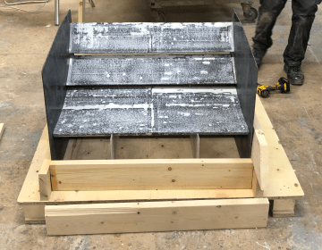
- Each endplate weight 850 gram after cast.
Brackets
- Airfoil brackets(AR20_A03_03/04) and “Mohawk” brackets(AR20_A03_07) were made by an external company.
- Main airfoil brackets(AR20_A03_05) and plugs(AR20_A03_11/13/15) were made in house in CNC, milling and drilling machines.
- Frame brackets(AR20_A03_06/14) were made in house with cutting plates and hand drill
- Carbon tube(AR20_A03_07) were bought from EasyComposites.
Mounting/Assembly
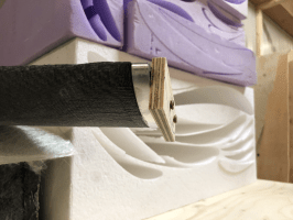
- Made a jig of woodwork and plexi for the wing assembly that putted pressure on the main airfoil.
- Bolted both flaps to the endplates and glued the main airfoil with epoxy.
- The wing assembly were then ready for dry-fit to the frame.
- Drilled four holes in the main airfoil for the main airfoil brackets(AR20_A03_05) and plugs(AR20_A03_13).
- Dry-fit started with placing the rear wing in center of the frame, the right height from the ground and the right distance from the back side of the rear bulkhead.
- Then the main airfoil brackets(AR20_A03_05) were plugged(AR20_A03_13) in place and the “Mohawk” brackets(AR20_A03_07) where bolted in place.
- Then the upper frame brackets(AR20_A03_06) were cutted/fitted to the right length and welded.
- Then the plug(AR20_A03_11) were bolted to the “Mohawk” brackets(AR20_A03_07).
- And the lower frame brackets(AR20_A03_14) were bolted to the carbon tube assembly (AR20_A03_10/15).
- Marked the right length of this assembly and cutted to fit.
- Connected both plugs(AR20_A03_11/15) to the tubes(AR20_A03_10) and welded in place.
- After this the upper plug(AR20_A03_11) and the underside of the main airfoil. brackets(AR20_A03_05) were glued with araldite and putted under pressure, shown in the picture(Make sure the glue is fully cured before removing the jig).
Testing
Hopefully
Next year
Next year the focus should be to optimize the airfoils angles, length and width. For the main airfoil the chord length was set to 400 mm. This is a length that can be tested further. Angle and overlap with flap 1 was tested with useful results. For flap 1 the chord length was set to 200 mm. This can also be tested further. Differents angles was also tested with a range of useful results that can be useful. Overlap and gap was also tested, but these reults can be tested deeper. Flap 2 is nearly the same as flap 1, with chord length set to 180 mm, and the angle range has useful results, but the overlap and gap can be tested further. Based on research the angle of attack(AOA) should be in the range 25-40 degree. Endeplate design is also something that can look deeper into. Some tests were done this year, but the results were not so accurate. Gurney flaps and sideflaps(vortex) are interesting things for further years.