Our members are still working despite the situation we find ourselves in right now, and in honor of the good work that our team members are doing, we want to highlight some of the best contributions to our new wiki page.
The wiki page is going to help us develop as a team, to learn from previous experiences
Frame
Ørjan Øvsthus
Member of chassis department
Managing: Primary structure
The frame, aka. Chassis, is the biggest single component of the car. It is the main structural member of the car, where all the other components are attached. As an engine could be called the heart of the car, a frame could be called the skeleton of the car.
This years frame is based upon the bachelors thesis “Optimization of a Formula SAE Space Frame”, made by 4 members from the AR19 team. Some adjustments were made to the design, but it remained mostly similar.
Concept
The thesis studied four different concept
(1) Weight reduction
(2) Torsional stiffness
(3) Round vs square tubes
(4) Focus on suspension/different geometry
Concept (4) was chosen due to the desire to place all loads from suspenstion in nodal points.
Not the lightest nor stiffest concept, but a great combination of all four and a key factor was the placement of nodal points with repsect to the suspension.
Design
The original plan was to introduce a pushrod front suspension system with AR20, so some modifications were made to the frame in order to make this possible. We also altered the front bulkhead in due to FS-rules considering the Front Wing (max 700mm from front tire to front-end of the front wing). The pushrod suspension would impair the view of the driver, so it was scrapped. Pushrod suspension is achievable, but it would need modifications to the front bulkhead support. We also reverted the changes to the bulkhead, as FS-rules would not allow the modifications made, and we managed to fit the front wing with a design more close to the one from the bachelors thesis.
Original Design
The original design included a K-shaped cross on top of the “front bulkhead support”, in order to support the front suspension system including an ARB(Anti-Roll Bar). This meant that the rockers would have to be placed on top of the “front bulkhead support” and with the current frame design, this would impair the driver’s vision. Therefore, the decision was made to change the suspension system which meant that we could remove the “K-cross”.
The changes to the front bulkhead included an “upward bend” on the lower support member 150mm behind the front bulkhead. This bend was made to fit part of the front wing under the frame. FS-Rule T 3.14.1, regarding the front bulhead support, states that “the lower support member must be attached to the base of the front bulkhead and the base of the front hoop”. The rules does not mention anything about the tube having to be straight, but after consulting with some FSAE judges, we had to revert the change as they did not approve of the design. Luckily, with some changes to the lengths of different parts of the car, we were able to fit the wing to a design closer to the one from the bachelor’s thesis
Final design
The final design of the frame ended up being quite similar to the bachelor’s thesis. Changes include: Raising the lower support members of the rear bulkhead, lowering and widening node-point on the sidewalls of the front bulkhead support, small adjustments to the heights of the hoops and the front bulkhead, ect.
Final design
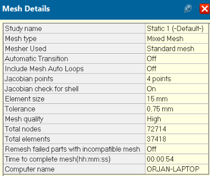
We ran an “Finite Element Method” (FEM) analysis on the final design to ensure that the frame’s torsional stiffness was above our requirement of 600Nm/deg. The analysis was performed using Solidworks 2019, on an assembly with the AR20 Space frame and AR20_C05_RearBulkhead.
The FEM analysis is based off of the bachelor’s thesis: “Optimization of a Formula SAE Space Frame”. For the mesh, we used the same parameters as in the bachelor’s thesis: 15mm, with 0.75mm tolerance. The assembly was held at the rear bulkhead suspension points and a force of 250N was applied at the front suspension points.
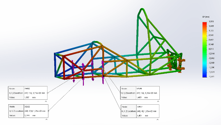
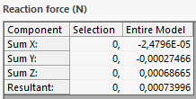
The torsional stiffness was calculated by finding the average torque, and average torsional angle of the front suspension points and then dividing the torque by the angle. The results showed a torsional stiffness of 1202[Nm/deg] which is twice the torsional stiffness needed.
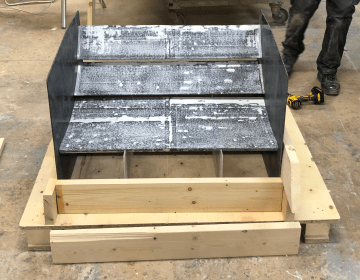
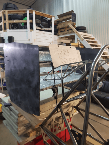
Production
Production of the frame was done in house, except for the bending of the hoops. ME Racing, our tube supplier did the tube bending for us, which spared us for alot of work. We decided to order 50% more tubes than what was strictly needed for the frame, which proved to be a smart move as several of the tubes proved to be quite difficult to fit.
The steering column bracket was made from two 28.57X1.45mm steel tubes and a sleeve machined from a steel piece. This sleeve and the steel inserts for the rear bulkhead are made in lathe, and can/should be made before the construction of the frame starts. The sleve had a brass insert in it and had to be made to fit this insert. The suspension team should be contacted regarding dimensions fir this sleeve.
The frame is the bracked of everything else on the car and it has to be right. Measuring is key to getting the dimensions right.
Hoops
The front and main hoop was bent for us by ME Racing in sweden as we did not have the right equipment for the job on Campus. We just had to make production drawings for them. The hoops are a crucial part of the frame and you want to get them right the first time, as getting new ones from sweden would take time that we don’t have. Therefore, we decided to make the hoops taller in the drawing(extend the tube ends), so that we could cut them ourselves when welding the frame.
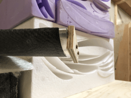
Notching
To notch the tubes, we “opened” all the tubes of the frame, and printed them out in size 1:1 with a printer at “Bygglabben”. The paper tubes was then cut out and wrapped around the steel tubes so we could mark how the notch was supposed to be and we would also get the correct length of the tubes. Then we cut the tubes and notched them using a tube notcher. We had to use grind some tubes to the right shape as the tube notcher couldn’t do it.
It is important to mention that almost all the tubes required grinding in one form or another to fit perfecty in the frame. This is adjustments that had to be made on site while building the frame in the welding jig. It was time consuming work and this is also why we had to scrap several tubes to get it right as the frame is TIG-welded and gaps are not desirable.
Improvements
Look into the possibility of getting the tubes CNC notched as this was exrtremely time consuming work. Try to find a company that has this kind of equipment and expertise.
The frame could have been lighter if we had used the tube dimensions from the bachelor’s thesis(ME Racing has these dimensons in the same material as AR20’s frame.) This would make the frame lighter without other modifications.
The SES might have some example designs of front bulkhead support structures that would be more compatible with pushrod suspension in the front if this is desirable.
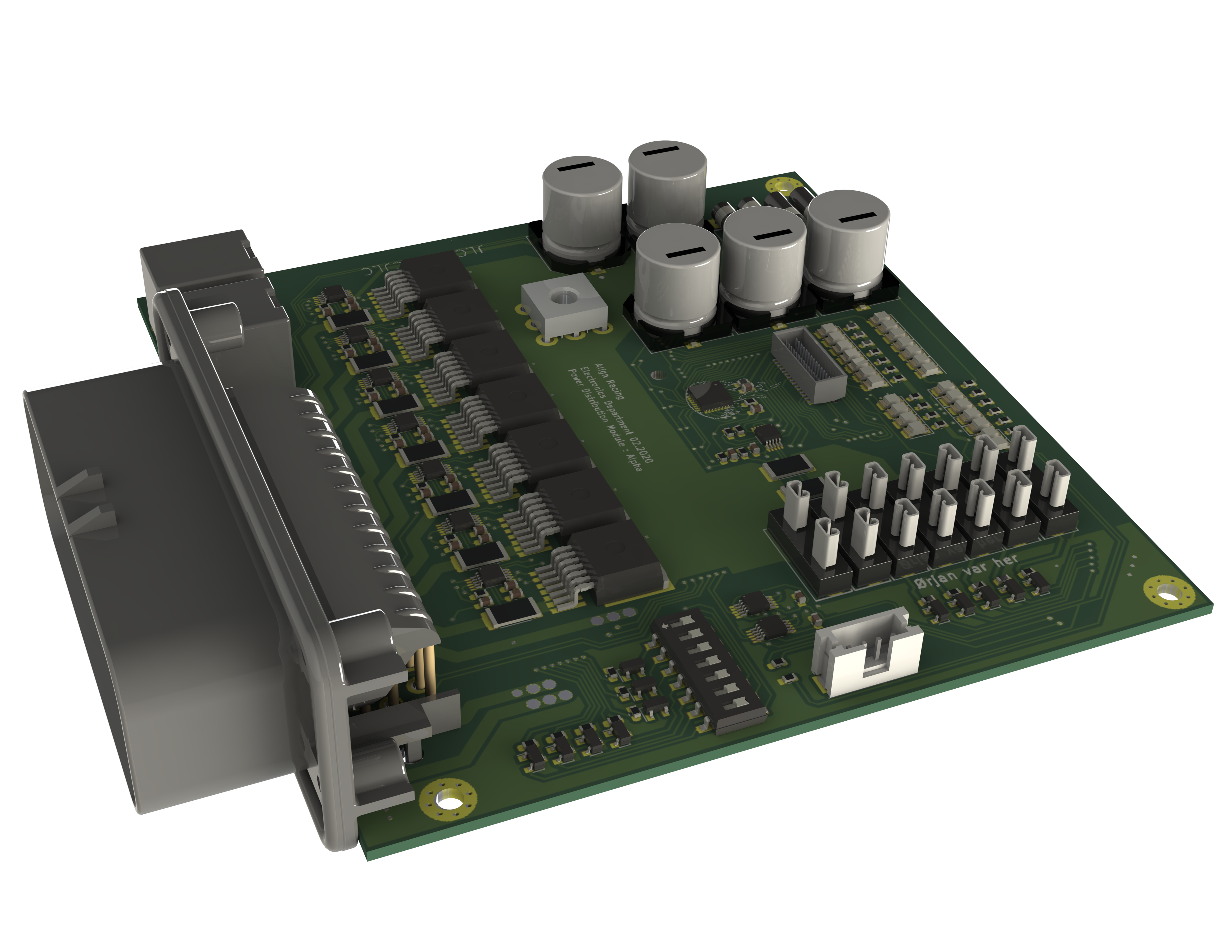
Power Distribution Module
Christian Salem
Member of Electronics department
Managing: Power Electronics
Power Distribution Module [PDM]
| Max total current: | 80 A |
|---|---|
| Max phase current: | 15 A |
| Phase count | 7 Fused Direct 7 Fully Digital 2 Shutdown Circuit Relays |
| Price Approx | 1500 Kr |
| Approximate weight | Guess: below 1 KG |
Why a pdm solution ?
PDM- power management module. Is a module where power is routed, switched, monitored, and more. Traditionally this is done by having separate fuses and relays connected together with traditional wires. And then controlled by a a separate controllers via signal wires. This is not space efficient and heavy. This is due to all components having individual cases, and a separate mounting hardware. In addition all connectors, cables, and cable management makes a big impact on space usage and weight. By integrating it all onto a Printed circuit board, we can considerably reduce the size and weight.
Every component looses its own mounting hardware and connector, and all of the bulky wiring is replaced with copper traces.
Components such as relays, and fuses is often available in circuit-board packages, often much smaller than standalone counterparts.
A PDM may switch or/and control many of a cars electrical systems. For example, fans, pumps, lights, actuators. Removing the need for separate controllers.
A such solution opens up a lot of opportunities. There is lot of technology available that can be integrated on a PCB, making for a future-oriented solution
Mechanical vs solid state components.
A pdm can be made purely mechanical. Meaning it consist of electro-magnetic relays, and traditional wire fuses. This type of pdm is predicted to be cheep, and easy to manufacture. This is also our backup plan. If we fail to develop a solid state PDM, it would be easy to fall back to this design.
In contrast, mosfets instad of relays, in combination with electronic fuses. This makes the system considerably smaller and lighter. In adition mosfet switching opens up possibility for PWM control, and advanced monitoring. However this is predicted to be lot harder to develop, and have a higher development cost. This is the solution we aim to develop this year.
Requirements , and a brief explanation:
PS: This applies only to the solid state pdm. If we fall back to our backup plan, none of this is valid. If we fall back to our backup plan, the only thing valid, would be to get a working, reliable car with traditional relays, and fuses, as discussed in “Mechanical VS solid state” paragraph.
This is a brief explanation, not a in depth reasoning. Please read the full technical documentation of the PDM, to fully understand, and to get the whole reason behind each choise.
– High Side Current Fusing and Switching. Any overcurent protection switch, needs to be placed highs side, in order to protect the whole system.
In addition, grounding can be done to frame, or directly to battery, instad back to PDM, saving a lot of weight in wires. This is how all professional PDM works.
– selectable amperage fuse / Over Current Protection.
Of Course we should be able to change the fuse value. Our PDM is designed flexible to allow multiple configurations, the fuse should be able to change values.
– Latching upon error, resetteble by a switch or eqv. (Applies to electronic fuses only)
Like any good fuse, our electronic fuses should be able to latch upon error, without it automatically reactivating into a short circuit. Automatic reactivation is sometimes desireble so we do not exclude this. However we should at least be able to latch it, if we would desire it. In fact, our current configuration of electronic fuses support both. Also we need some convinient method of resetting the fault.
– Switch or eqv. that turns off a particular circuit (Applies to electronic fuses only)
For troubleshooting purposes we should be able to deactivate a particular Phase/Circuit.
Same as removing a fuse in a regular setup.
– Indicator for fuse tripped/fuse deactivated
As it is impossible to tell whether an electronic fuse is tripped, just by looking at it, we need some sort of indicator to tell us.
Also we would like to know if a regular fuse is blown, just at a glance, without needing to disassemble the PDM.
Also in this case, we need some sort of indicator to tell us.
– Over current protection (OCP) done in components, not software. We have bent this rule! let me explain:
This is because of safety. At this moment, we think that programming reliably is a challenge. As OCP is one of the most important features, that prevents our car from catching on fire. Programming this feature is unneeded added complication, and a security risk. How ever we changed our mind a little.
Currently the OCP (Over Current Protection), it is done by a special IC chip. It triggers OCP without any help from a microprocessor, or any programming. However, it needs to be configured, every time the PDM is powered on. This configuration is done in software, violating this requirement somewhat. It is done so, because the chip we use makes for a small and neat PDM, has many nice features, and is generally future proof. Alltho somewhat complicated, we think that configuring it in software would be reliable enough, and that the most important and critcall part is still done in hardware. Read more about this in “Protection Section of the PDM”
– Externally controlled, without needing to program the I/O.
We would like to be able to control all the phases/Circuits of the PDM, externaly with simple signal wires (Aux Input). This is for redundancy, in case one of the systems fails, we have additional method of getting the car running. In addition if we fail to implement some of the systems in software or via can bus, there is always a backup method. A simple signal wire. For example : If we could not get the cooling system running via CAN bus, we could connect the PDM directly to ECU and switch it via a traditional signal wire. As of now, this is implemented. The program still handles configuration of the Over Current Protection, and thus needs to activate each input. This happens automatically upon initialization, and from then on, the aux inputs can be used, without any programming.
– Monitoring, and feedback, if possible.As monitoring is one of the advantages of having a fancy PDM, this is a kinda of a requirement. alltho if it proves to be a challange, we would not implement it. So its not really a requirement, but kind of. It still better to take a step further into the PDM technology, even tho without the monitoring, than omitting the PDM consept, just because lack of monitoring features.
Current Status:
Under development:
– Mosfets works like a charm, as well as i2C circuit.
– Need to test the fix for where AUX inputs was malfunctioning, on our newest PCB board. This fix is simulated in LT-Spice to work.
– Issue: where induced voltage is frying our monitoring chip. Solution: Add three resistors per monitoring chip to limit the current. Not yet tested.
Next is to test this solution, and incorporate it into the system.
Undertray
Martin Hermansen
Member of Aero department
Managing: Undertray
This is the first undertray designed and manufactured by Align Racing.
Concept
Since this was our, and Aligns, first time designing an undertray we learned that there are a lot of elements to consider. We started out with the following concepts:
Vortex generators
Vortex generators are primarily used to keep the flow attached, they can also be used as barriers to prevent flow entering the low-pressure zone under the vehicle. If air enters the low-pressure zone turbulence increases which leads to increased pressure. However, it may be an advantage to have vortices rolling up the diffuser to prevent the flow from separating. If vortex generators are low cost, easy to produce and implement, we should consider it.
However, the need for simulations with and without VGs are necessary to come to a conclusion.
Attachment method
We felt we had to think about this because we pherhaps could find a genius way to mount it. We talked about it for some time, but no one came up with any other good options but the obvious one.
Brackets and bolts.
Mould production method
On this concept 3 options are considered: Machined mould, Homemade mould and Homemade foam profiles. Firts comparing the weights of the options, two of the options stand out. Both moulds would be lighter than the homemade foam profiles. Regardig price, the first options is the worst. It is really expensive to order a machined mould from a professional manufacturer. The two other options scores higher on this point, beacuse manufacturing in house is consideribly cheaper. However. The in house capabilities are low and time consuming, in addition the quality will be lower. This will impact perfomance on the finished product.
Since perfomance is crucial, a machined mould would serve as the best option for our case. If we in early stages get a contract with a manufacturer, it is likely that the prices will be manageable.
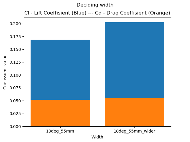
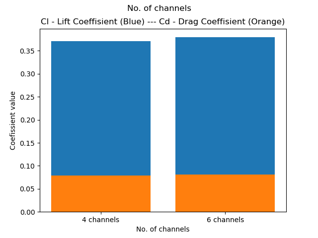
Number of undertray channels
One could say this is a design phase concept. But it was chosen to write a report of it because the different solutions creates different problems for other groups. Since this is going to be the first year with focus on aerodynamics we think that it’s important that we get a positive effect on the vehicle, that helps to improve the overall result of the car. Because of this we are thinking to go with the option that we think is the most doable at the moment. Therefore we need an option that we can fit and mount on the car w/o extremly much trouble. And the option has to have space so we can change the profile of the diffuser if we have to. Could be because of the simulations doesn’t give the results we want.
We are going for option because we think that we can get the most performance from this option this year. Wich is one channel is the middle that splits.
* In the design phase where a lot of CFD testing were done. This was changed to six channels due to performance and being able to jack up the vehicle.
Design
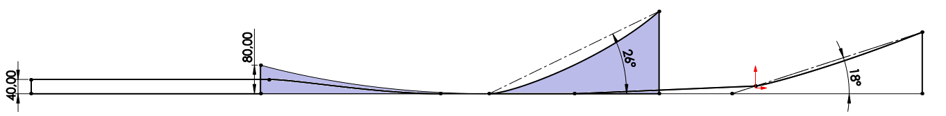
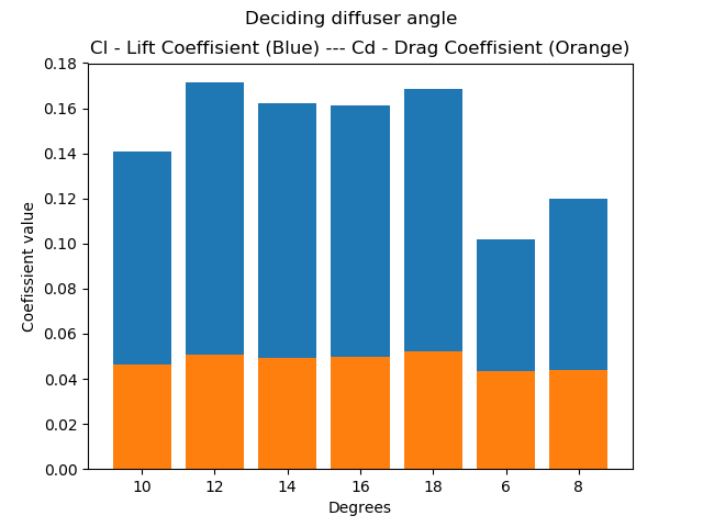
The way the design of the undertray was attacked, was by isolating the most important factors that affects for downforce and drag, then tuning those to deliver the best results individually. The factors chosen was diffuser angle, flanges, jackingbar, skirt, smallest and largest area ratio, length, width, and strakes. When feeling confident with a result in CFD testing, the factor was locked in the SW-drawing. By continuously doing this the undertray started of looking quite “naked” until every factor was CFD tested and locked.
Diffuser angle (18 degrees): On the diffuser angle we did alot of testing, one should try to stick between 17-21 degrees.
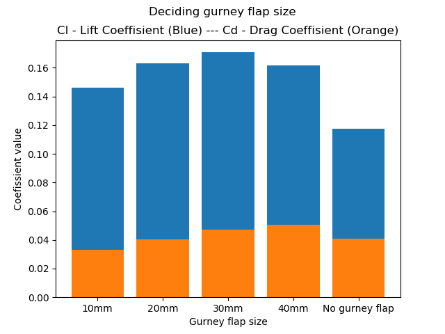
Gurney flap (30mm): The analysis showed us that around 30mm of gurney flap is good.
Jackingbar: One should try to avoid jackingbar inside diffuser at all cost! Destroys much of the diffusers purpose.
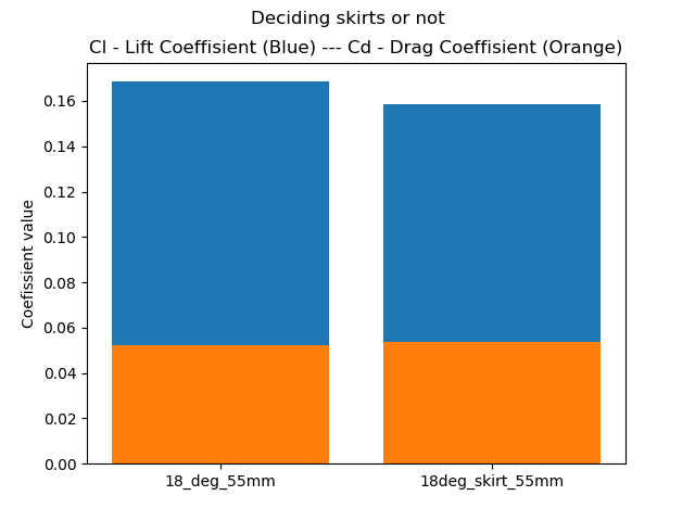
Skirt: Along the edge of the undertay one can have a “skirt”, this is used to force the air to stay underneath the car, and don’t exit out on the sides before reaching the diffuser. Due to our allready low ride heigth and a no-go on touching the ground in race, we found that it was not worth.
Smallest and largest area ratio (4-5): This ratio is pretty important, and is written alot about in different aerodynamic books. If one makes two rectangles from the ground up to the diffuser. Where one is at the begining and the other one in the end of the diffuser, these should have a ratio between 4-5. The rear rectangle should be 4-5 times larger than the one at the start of the diffuser. In our case we can just measure the heigth because the width stays the same.
Length: The longer your diffuser are, the steeper your diffuser angle can be.
Width: The wider the undertray is, the larger surface area you get underneath the car. Then the “sucking force”, based on Bernoulli’s principle, has a larger area to work on. So one should try to have as wide undertray as possible.
Strakes (5): Decided to go with 5 strakes because then these would be strong enough to jack up the car. The effect this has on the downforce and drag is minimal.
* Whats wrong by doing this is that the factors affect eachother. Since there was nothing to go on from previous years, this sacrifice was made.
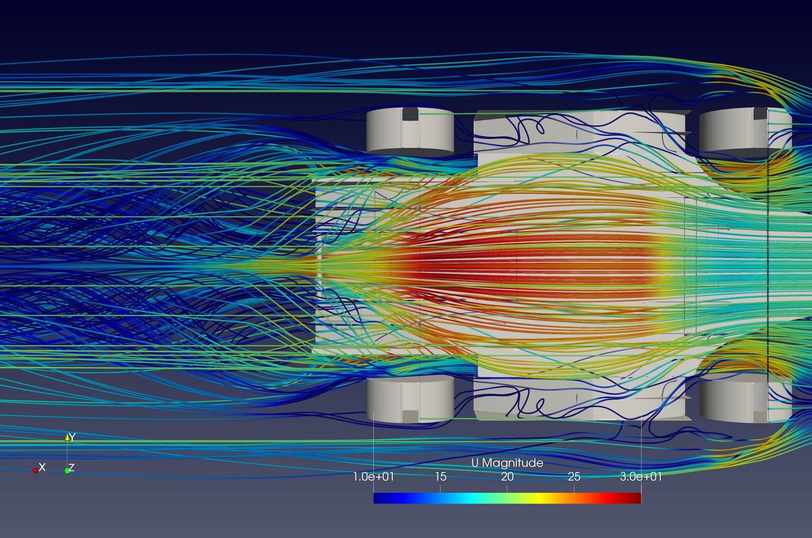
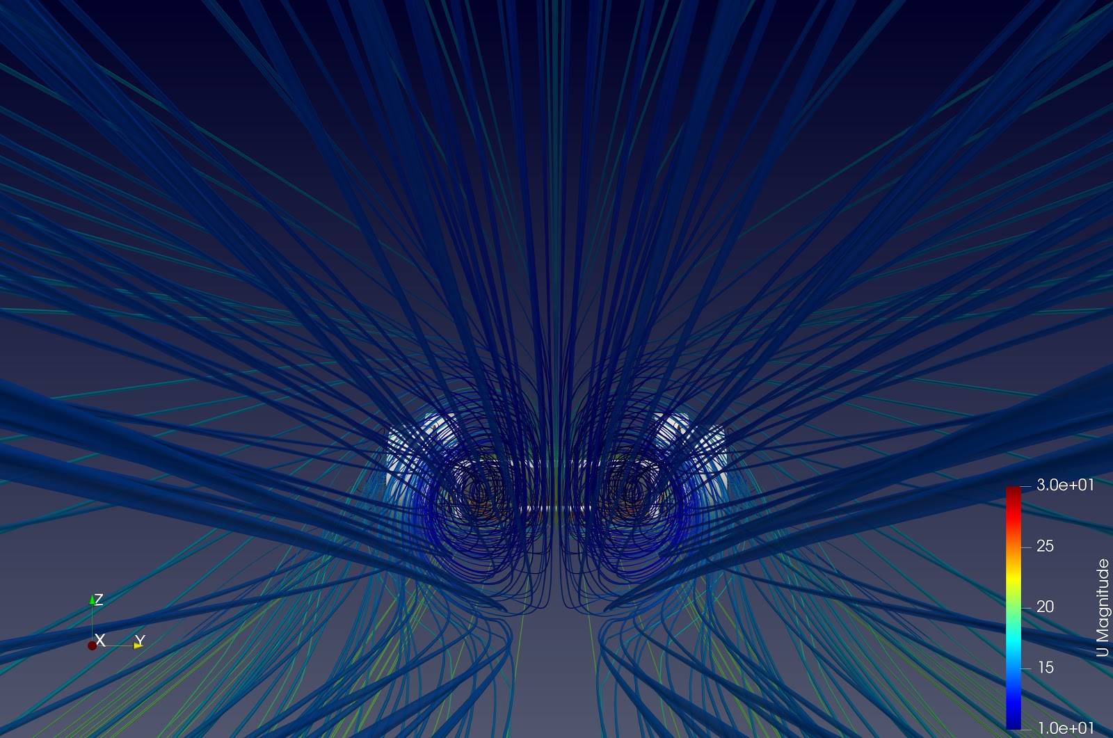
CFD
* All CFD-analysis of the same factor was done with the same boundrary values, but we changed them for testing between each factor. Therefore one can compare values of each factor, but not values from factor to factor.
Diffuser angle (18 degrees):
Gurney flap (30mm):
Jackingbar:

Skirt:
Width:
Strakes (5):
Smallest and largets area ratio (4-5): N/A
Length: N/A
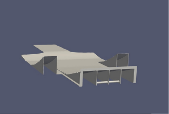
Airflow
Pressure
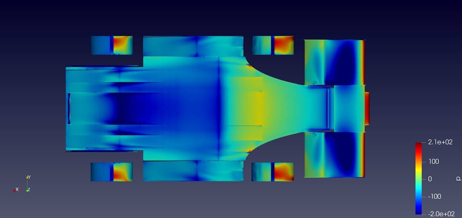
Production
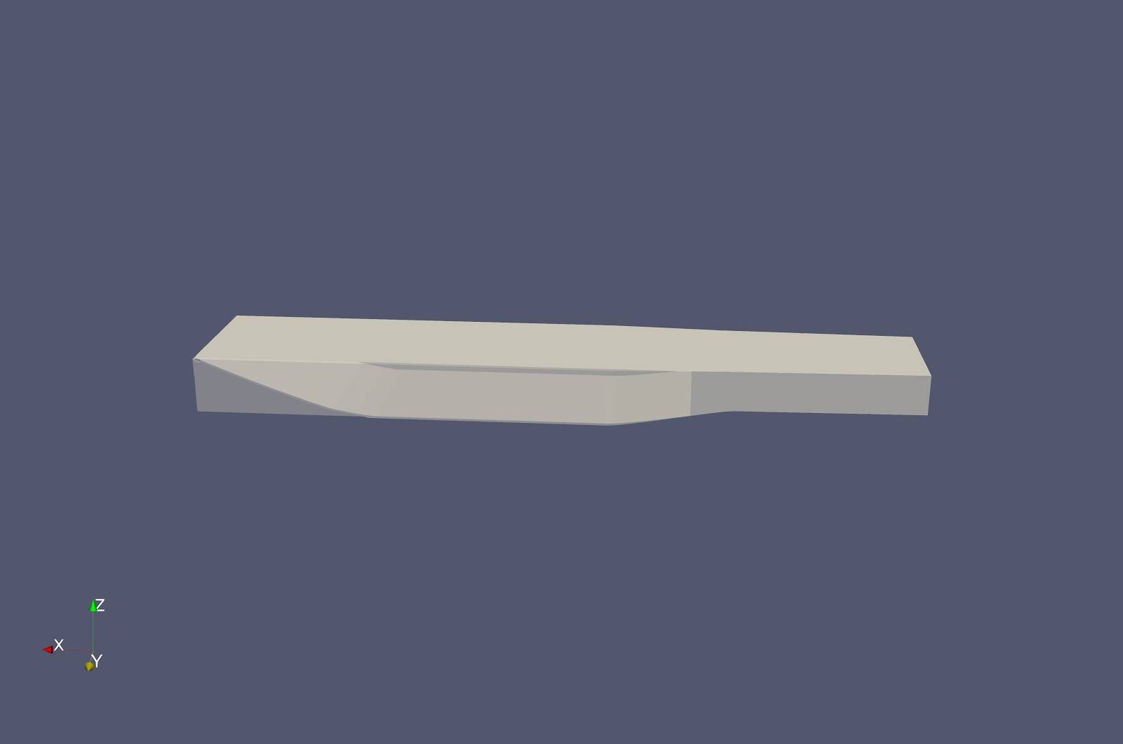
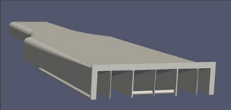
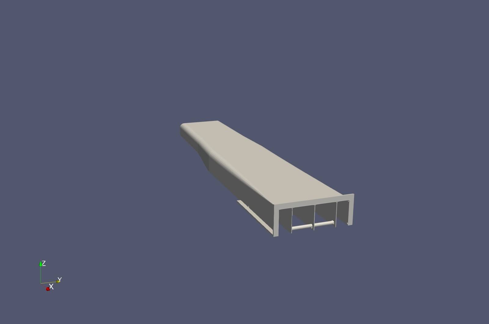
Undertray (AR20_A04_01)
The undertray
Since we aren’t finished yet due to COVID-19 we can’t quite tell if the production method will be going to plan. But the plan is to honeycomb two thin carbon fiber undertray parts together, this will add stiffness and still keep the weigth low. This has been a succses in testing, and with the production of the strakes and endplates.
Gurney flaps:
The gurney flaps are made out of carbon fiber sheets. After we cut them in the appropriate measurements we firstly glued them onto they undertray, then we used a method called wet-layup to cast the gurney flaps and undertray together.
Strakes:
The production of the strakes started by laser cutting a piece of plexiglass to have an exact model of the strakes. Then we casted some thin sheets of carbon fiber and “honeycombed” these to increase the stiffness, but at the same time keeping the weigth to a minimum. Later they were cut with the help of the plexiglass model to be correct size. Now there were five strakes that needed a bit of sanding before we casted them into the undertray with the same method used with the gurney flaps. However we had to use a mockup we made out of wood to make sure they were casted into the exactly rigth location.
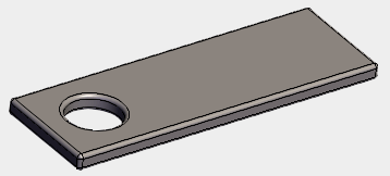
Rectangular brackets (AR20_A04_02)
Made by hand out of steel. Welded on.
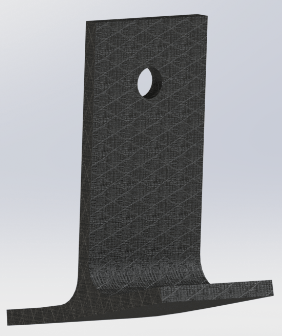
T-brackets (AR20_A04_03)
The T-brackets are made of carbon. We milled a mold of the bottom half out of polyurethane, then casted those into carbon. When we had the bottom half in carbon, we casted some thiccccc carbon plates perpendicular onto the bottom half. After this, we had the T-brackets. But we wanted to be sure that they were strong enough, therefore we wrapped the hole bracket in carbon once more and did a wet layup. Then we had the complete brackets.
Rear wing
Henry Jensen
Member of Aero department
Managing: Rare-wing
Rear wing is an aerodynamic device mounted at the rear of a car. The job of the rear wing is mainly to get the most possible force against the ground (downforce), with the least possible force towards the direction of travel (drag). This is the first year we implement this kind of device on our car. Therefore our main focus has been to get the foundation for this type of development.
Concept
- Wing/No wing:
- Wing: The reasons for producing and using a rear wing are mainly performance gains, and marketing advantages. These reasons are higly weighted, as they play a vital role in our performance this year and the years to come.
- No wing: If budget is too tight, wings could be postponed until next year or the year after. As wings probably will be implemented soon anyway, we believe it should be done as early as possible, and if the budget will allow it, we have the knowledge and motivation to do so this year.
- Conclusion: Decided to go for wings, both rear and front. It gives better lap times, more design presentation points, more attractive to sponsors, better feeling of accomplishment for the whole team, as the car will look quite different to last year, and presumably quite spectacular.
- Wing production:
- Hollow: A hollow airfoil can be produced by pouring a chemical (acetone) into an already produced foam airfoil. The result is therefore a little more expensive and requires a little more work. In scenarios far above the CG, such as rear wing, a hollow airfoil will be preffered. An Icelandic team has a good production list on how-to produce hollow wings.
- Styrofoam: Styrofoam can be a solution if the budget gets very tight. I can possibly produce desired downforce, but amount of lost performance still unclear.
- High-quality foam: Compared to styrofoam, high-quality foam has a higher quality, and is therefore a bit more expensive. It is cheap to buy in large quantities, and will give us the training requred to master the techniqe and skills required to produce acceptable quality airfoils.
- Conclusion: A hollow airfoil can be used on the rear wing, due to low chance of impact damage and due to CG of the car. This is a much cheaper and lighter option then foam. These are early thoughts, and further research and analysis may alter the conclusion. (e.g. weight of hollow airfoil vs weight of foam-core airfoil with similar strength. It may prove beneficial to use foam core also for the rear wing). Decided to go for foam inside the wing. Not the most optimal option, but a safe option.
- Wing attachment method:
- The wings at the front and the back must be rigidly attached, unless one has to experiment with floating wings. Metal or carbon brackets are most commonly used in FSAE, which is perhaps the best way to attach the wings to get it completely rigid. Rods and wires are most commonly used to support when distances are too large to use a bracket. Attaching the aeropack directly to the frame or body is, by little research, not much used. This method requires a lot of planning in the design phase, and this years this time was rather spent on getting a airfoil design that could work.
- Conclusion: Therefore it was decided to go for aluminium brackets as the main bracket and some additional support such as carbon tubes and wires.
- Wing assambly method:
- Insert on the outside of the airfoil: This option has an edge/flange that rests on the wing profile. This can destroy the air flow that comes over the wing, but this is, at this stage, very early to say. Potentially, this may not be a problem. This is just as easy and cheap as the option with the insert inside. However, this option can be easier to replace, as well as being very easy to manufacture. You can, if you find that these can be 3D printed, create new ones right up to the competition. You don’t have to do much with the foam (it can be bought / made and molded to finished length). Maybe it can just be laid on the outside without being glued? It can also “hide” nastly edges from both side of the carbon/foam mold.
- Insert on the inside of the airfoil: This is a very clean alternative. It does not ruin the air flow, as well as being very light. The problem with this option is that it can be difficult to produce. Not the insert itself, but putting the insert in place. This requires work to design, making production simple. In addition, it can be challenging if you want to replace the insert or change the attachment points.
- Carbon reinforcement: This is a very smart option, where you just mold carbon reinforcements on the wing profile and glue the insert. This is very simple and inexpensive, but maybe the ugly edges on either side, which give height differences, can be a problem. Here you also trust that the glue and foams can withstand the loads that arise. This option also requires a lot of work shown to change the attachment point. Then you could potentially end up having to re-create the entire wing profile.
- Conclusion: It were decided to go for inserts inside of the airfoil. Aluminium brackets that were glued on both sides after the wing was finished casted.
- 2D airfoils:
- Conclusion: All same profile and flat endplates because easy to design, cost effective, easy to manufacture and with high chance of similarity between design and product.
Design
CFD/Airfoil selection
- 2D CFD of airfoil types at different angles(0-16 degrees) to decide which to use, together with ease of manufacture (thickness of trailing edge). Decided E423 for all profiles. The different results for the different types is shown in the graph below. The reason for not to choose MSHD or S1223 is the difficult production because of thin edges.
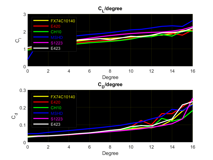
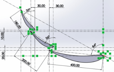
- Decided to go for 3 airfoils from the beginning. Most of the teams race with 3 airfoils and the CFD supervisor also recommended 3 airfoils. Also the chord length was set to 180, 200 and 400mm to minimize the number of variables in the flow simulation. Then 2D CFD of different concepts of airfoil positions(Angles, overlap and gap). The final results is shown in the picture below.
- Some tests were done this year about the endplate design also, but the results were not so accurate. Gurney flaps, sideflaps(vortex), extra airfoil and airfoil outside of the endplates was simulated. All gave better results, espesially gurney flaps and sideflaps, but was left out because of the uncertainty surrounding the need to firstly make something and then add stuff.
Production
Airfoils(AR20_A03_01)
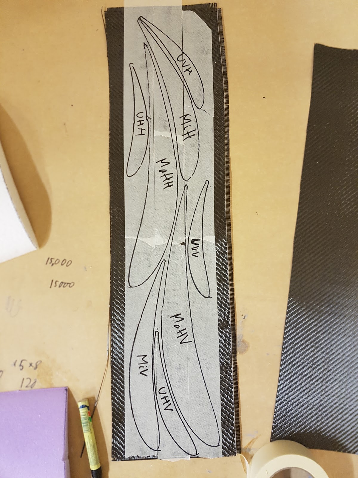
- Started with pre-cut airfoil profiles in foam.
- Glued the airfoils together with araldite (black) glue. Used toothpicks to prevent the parts from slipping apart.
- Cut the wings to finished length.
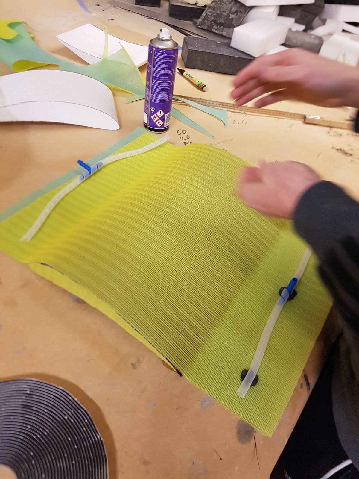
- Fold a layer of thin carbon fiber around the airfoil profile with spray glue.
- Cut out airfoil profiles in carbon fiber and glued on each side (tape worked really well to hold the carbon fibers in place).
- A layer of spreading cloth under and over the wing profile in a kind of sandwich. It is important here to place the end of the
cloth outside the wing, or there will be bad marks in the wing from the spiral tubes.
- Cut out airfoil profiles of the spreading cloth and glued on each side (here no tape is needed to keep the cloth intact).
- Spiral tubes on the airfoil just outside the trailing and leading edge.
- Packed the airfoil in a plastic bag. Important to have a lot of plastic, especially on the sides.
- Pulled the epoxy from leading to trailing edge.
- Main flap weight 870 gram after the cast.
- Flap 1 weight 390 gram after the cast.
- Flap 2 weight 270 gram after the cast.
- Carefully sanded the sides on Flap 1 and 2 to prepare for gluing.
- Glued both airfoil brackets(AR20_A03_03/04) to each flaps and screwed some screws through a wood plate and in to the carbon airfoil to hold it to place.
- Spraysparkled all the wings with two layers.
- Sanded the wings with 240 paper(120 can be used if the layer is really thick, be careful to sand into the foam, but sand a little bit in to the carbon is fine, just keep looking at the sand dust).
- Hand sparkled all the wings two times to get sufficient look.
- Sanded the wings with 120 paper and one fine pass with 240 paper.
- Drilled further down in the airfoil brackets to make sure the fully threads.
- Threaded M5 in the airfoil brackets(be carefully not go to far down, just make threads in the aluminium).
- Glued the airfoil brackets to the end of the two upper airfoils. Used a piece of wood to hold it on place.(This glue does not anything that is warm)
- Then the airfoils is ready for mounting.
Endplates(AR20_A03_09)
- Started by making 4 oversized carbon plates with two thin layers of carbon cloth(used a glass plate to get good finish on one side).
- Rough cutted the carbon plates.
- Glued the “backside” of ONE carbon plate to honeycomb with epoxy(one thin layer of epoxy is enough). Put it in pressure(be careful to put press on the honeycomb side without a plastic bag between, this prevent the honeycomb to be glued together with the thing you use to put pressure on with).
- Glued the “backside” of the last carbon plate to the half finish sandwich and put it in pressure.
- Printed and cutted out 1:1 A0 paper of the wings.
- Used the cutted paper of the wings to mark/sketch where to cut the wings to finishing shape.
- Sanded the endplates with 240 paper.
- Printed and cutted out 1:1 paper of the airfoil brackets.
- Holded the cutted paper of the airfoil brackets over the airfoil brackets to mark/popped out the holes.
- Holded the cutted paper of the airfoil brackets over the cutted paper of the endplate, and over the real endplates, and marked the 4 holes.
- Drilled the four holes.
- Each endplate weight 850 gram after cast.
Brackets
- Airfoil brackets(AR20_A03_03/04) and “Mohawk” brackets(AR20_A03_07) were made by an external company.
- Main airfoil brackets(AR20_A03_05) and plugs(AR20_A03_11/13/15) were made in house in CNC, milling and drilling machines.
- Frame brackets(AR20_A03_06/14) were made in house with cutting plates and hand drill
- Carbon tube(AR20_A03_07) were bought from EasyComposites.
Mounting/Assembly
- Made a jig of woodwork and plexi for the wing assembly that putted pressure on the main airfoil.
- Bolted both flaps to the endplates and glued the main airfoil with epoxy.
- The wing assembly were then ready for dry-fit to the frame.
- Drilled four holes in the main airfoil for the main airfoil brackets(AR20_A03_05) and plugs(AR20_A03_13).
- Dry-fit started with placing the rear wing in center of the frame, the right height from the ground and the right distance from the back side of the rear bulkhead.
- Then the main airfoil brackets(AR20_A03_05) were plugged(AR20_A03_13) in place and the “Mohawk” brackets(AR20_A03_07) where bolted in place.
- Then the upper frame brackets(AR20_A03_06) were cutted/fitted to the right length and welded.
- Then the plug(AR20_A03_11) were bolted to the “Mohawk” brackets(AR20_A03_07).
- And the lower frame brackets(AR20_A03_14) were bolted to the carbon tube assembly (AR20_A03_10/15).
- Marked the right length of this assembly and cutted to fit.
- Connected both plugs(AR20_A03_11/15) to the tubes(AR20_A03_10) and welded in place.
- After this the upper plug(AR20_A03_11) and the underside of the main airfoil. brackets(AR20_A03_05) were glued with araldite and putted under pressure, shown in the picture(Make sure the glue is fully cured before removing the jig).
Testing
Hopefully
Next year
Next year the focus should be to optimize the airfoils angles, length and width. For the main airfoil the chord length was set to 400 mm. This is a length that can be tested further. Angle and overlap with flap 1 was tested with useful results. For flap 1 the chord length was set to 200 mm. This can also be tested further. Differents angles was also tested with a range of useful results that can be useful. Overlap and gap was also tested, but these reults can be tested deeper. Flap 2 is nearly the same as flap 1, with chord length set to 180 mm, and the angle range has useful results, but the overlap and gap can be tested further. Based on research the angle of attack(AOA) should be in the range 25-40 degree. Endeplate design is also something that can look deeper into. Some tests were done this year, but the results were not so accurate. Gurney flaps and sideflaps(vortex) are interesting things for further years.
Engine
Tine Eie
Member of powertrain department
Managing: Engine
The engine is the very heart of the vehicle, being the sole power source in most cases. Hence its functionality is critical for the car. The choice of engine is the same for AR20 as for AR19, namely the KTM 690 single cylinder engine.
Front engine mounts
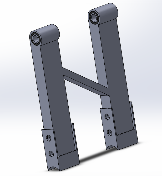
Concept and design
The front engine mounts consists of two main parts; an alu part which is directly fastened to the engine, and a steel bracket which is welded to the frame. The alu fasteners are reinforced with a square tube in between. Setting the concept for the mounts, the prime factor to consider was the fact that the engine would be lowered out of the car for AR20, as opposed to the solution for AR19 which included pulling it out from behind with the rear bulkhead. Therefore, the most significant change of design is the length of the brackets as they would intersect the engine otherwise. Another important difference is the bracket walls. They are designed with the intention of managing to extract the alu fasteners from the front. This allows the mounts to be removed with only a slight elevation of the engine as the alu fasteners clear the front bracket wall (~5mm).
Choice of materials
As mentioned in the previous section, two main parts comprise the mounts. The choice of steel for the brackets was a no-brainer, as they would be welded to the frame which, naturally, is made of steel. Choosing alu for the main fasteners was relatively easy to decide, although not a matter of course. The main reason for replacing steel with alu is weight reduction. Still, the engine mounts are rarely the components one chooses to cut weight on as their main purpose (and quite crucial) is holding the engine. But we made the decision that aluminium would be adequate for its mission, and for a greater sense of safety, the walls are relatively thick. The alloy used is 6082 as this is fairly sturdy for aluminium. 7075 is notably stronger, but lack the welding friendliness.
Production and challenges
Starting to produce the mounts went relatively smoothly when considering the alu fasteners. A square tube was ordered and with a bit of cutting and milling the alu part was finished. The steel brackets on the other hand became more complicated. Originally, the plan for them was also machining them from a square tube. Unfortunately the access to the measurements was quite limited and a bulk had to be bought, which would be a quite significant expense, not to mention, unnecessary. So the conclusion was to make them from steel plates. There are quite a few downsides to this method. First of all, by welding at several places (in this case all four corners), one weakens the material significantly. Secondly, it is a lot more difficult to make them precise. Also, it simply takes more time. Naturally this was not the desired solution, but merely a method that works although not much more.
Rear engine mount assembly
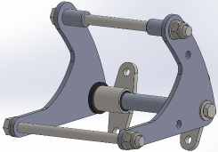
Concept and design
The rear engine mount assembly consists of 3 different parts bolted to the engine’s two existing bolt holes, the latter originally being used to mount the engine to the KTM motorbikes. We are not fortunate enough to have a narrow frame, which could easily have let us mount the engine in the traditional way (as in original KTM bikes). In this design we could have used the engine as a structural part of the chassis. Instead we utilize the car’s backplate to mount it. As seen on the 3D model, we used brackets with polyurethane bushings to dampen the engine’s vibrations into the chassis. This whole assembly is being held together by a hollow alu shaft which is intersected by a bolt to tighten the brackets, bushings and side plate/arms. Those two 10mm hols in the side plates are meant for clicktronic mounting.
Choice of materials
This assembly consists of many different materials. The arms/side plates are made of 7075 T6 alu for its supurb strength and its weight. Poly bushings are purchase at Powerflex Germany or UK and consist of 80 shore A, an alternative can be the 70 shore A. The bushing brackets are made of normal steel for its weld properties and its strength. This bracket is welded together by 3 different parts: bushing tube, square standoff tube, and plasma cut bolt flange. These are the critical material copies, the other bones are just what we had at hand.
Production and challenges
Production went relatively painless. I had some difficulties finding the right rectangle tubing for my standoffs which are one of the welded parts in the bushing brackets. I solved this issue by cutting down a square tube and then welding it together again. The other issue was that one of those bushing tubes got a bit egg-shaped when fitting it in the 4 jaw lathe, but I kept a lot of safety margin in the material because I knew that welding would cause some geometric issues. Especially warping of its bolting flange, which I prevented by putting it in a hydraulic press directly after welding (it was still red) and straining it by eye.
Cooling
Tom Erik Vange
Member of Powertrain department
Managing: FUEL AND COOLING
A vehicle’s engine-cooling system serves not just to keep the engine cool, but to also keep its temperature warm enough to ensure efficient, clean operation.
In other words, The cooling system keeps everything cool.
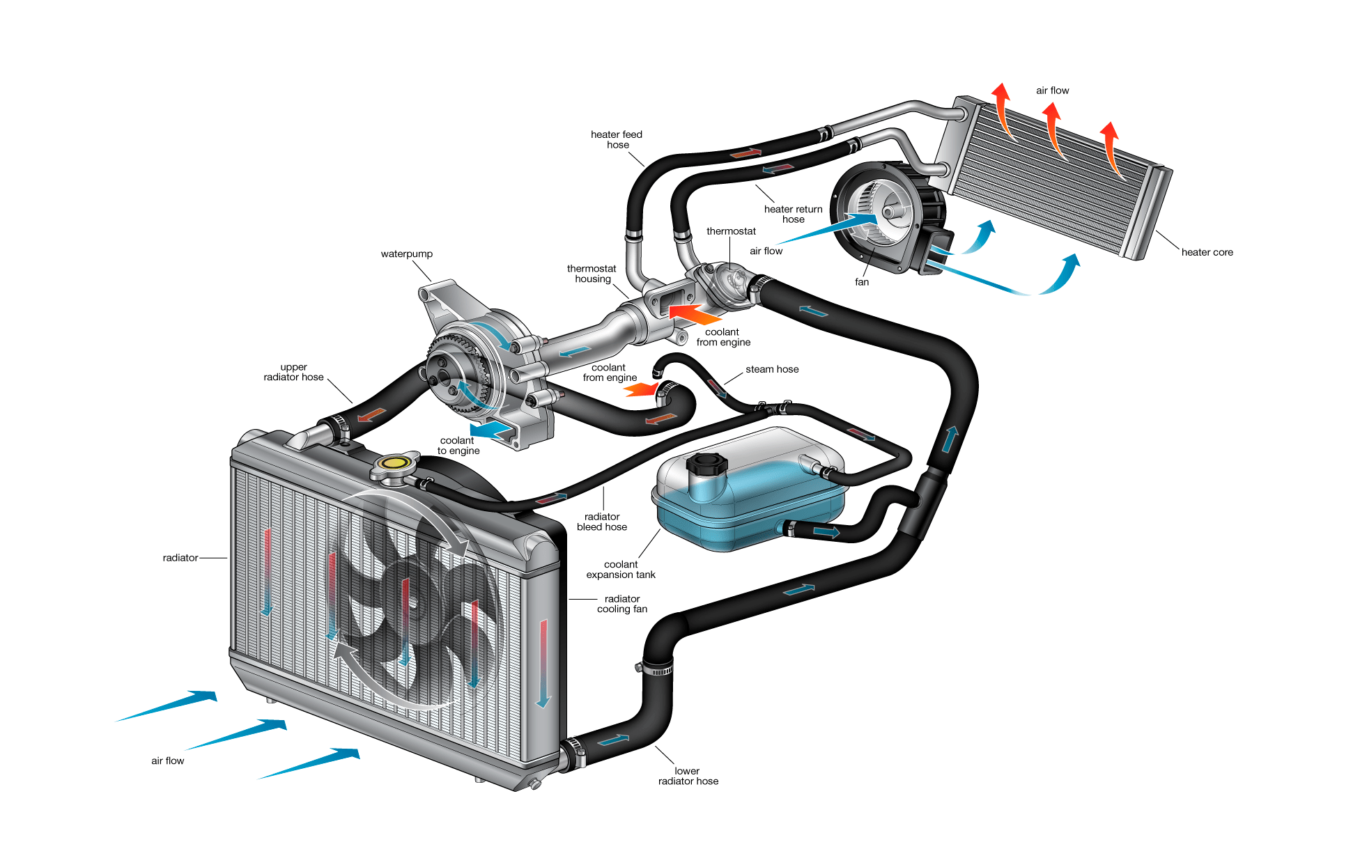
Cooling system AR20
This year’s cooling system was drastically downscaled in comparison to last year’s setup. We decided that we wanted to try with only one radiator, and an even smaller one at that. This was mainly because our engine had a hard time to heat up, and when the pump started, the temperature would drastically drop. For this year, we wanted to try pulse-width modeling with a smaller cooling system. The total amount of water in the system is calculated to be 1,5 L.
Components
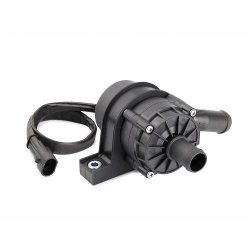
The radiator used on our car was donated by one of our sponsors, Grimstad Chiptuning.
The fan connected to our radiator was the same as the one used on AR19.
The pump used was of the type “EBP40“.
Since we had no sidepod on this years car, we made a ducting on the front of the radiator, and a fancowl from the radiator backside and to the fan.
Main rules and regulations
According to the rules of FSAE:
- We are only allowed to use plain water in our cooling system.
- The expantion tank/refilling has to be at least 10% the volume of the system.
- Any material used in the cooling system is required to withstand temperatures specified by the rules.
- The driver must be shielded from any possible source of spilling (and high temperatures around the cooling system).
Testing and verification
To test the effect of the cooling system, we rigged up a test-system with the radiator, cooling pipes and a bowl of boiling water on a stove. This test was used to find the Δt (difference in temperature) from when the water entered the system, and when it got out of the system.
There are also data from Solan (AR19) at endurance in the archive, where you can see that the cooling system was too effective. It should also be data from AR20 out in archive with the different senarios of no duct-no fan, no duct with fan, and with duct and fan.
Testing setup
For the test setup, a boiler on a oven was used. It is importen when testing the cooling system that the pump gets no air pocket in the system, so that it can manage to push the water around the system. This should also be in mind when designing the finished system on the car. Also take note that you don’t get airpockets in any pipes or hoeses.
Choice of components
The choise of components for AR20 was mainly for downsizing, less efficient and aiming for a lighter system.
Take a look at what the original motor came with of parts and specs. Aim for simmular setup, but also take into an account that the engine might get less air-cooling while riding, the use of a tubo and simular factors.
Also when choosing electrical components, be in contact wiht electro. It is important not to exceed the power-budget, so that the car can manage to drive entire endurance without the risk of draining the battery completely.
Radiator
The first radiator for AR20 was ment to be modified and converted into a dual-pass radiator (water crosses the core 2 times). Found a cheep radiator, and started designing the side tanks, but before the label started it got confronted that the radiator could not be welded, therefor it ended on the shelf. The reason for it could not be welded was it had bushings in it, which would melt during welding, and we would get several leaks.
Therefore:
If you aim for modifiing the radiator, get a core which can be welded, and design the side tanks from there.
There are not many radiator in the size like AR20 or AR19, (manly car radiators are too big, and mc radiators are a bit expencive) but there might me some aircondition radiator in this size (Fun fact: AR19 are aircondition-radiator from some construction machine, and AR20 are an aircondition-radiator from a mark 5 supra).
Take into an account the ports of the radiator and placement, considering potential leaks and air pockets.
Fan
The fan for AR20 and AR19 is the same model, which hase a great power, is fairly small and fit into the power-budget.
Pump
Since we tok aim at downsizing the cooling system compared to AR19, a smaller pump whas choosen. Davies craig has a great selection of pumps. The AR20 pump can pump 34 L/min. With the use of an electric pump, you can run the cooling system, even if the motor is off. The pump can me PWM (Pulse width modulation) so you can get f.instance 3 setting where the pump can go slow, medium and at full speed, depending of the engine temp. Talk with electro for such a setup.
Tubing
For AR20 the choice of using pipes instead of hoeses where made for saving weight. Tip: Use AN-fittings. It will make it easeier for setting up and changing parts in the system and assembly.
Depending of the pipes size and thicknes you might need to cut and weld, or maybe bend it. The technique used on AR20 whas bending with the help of filling the pipe with sand, cap’ing both ends, warm the pipe up with a heat gun and use a “pipe-bender” at UIA’s lab. (simular to this, except we clamped the ends with a vise, and filled with sand from the beach).
Aim for around the same pipe size as the engine outlet. Then use silicon hose at all transition needed. Make sure that the claps holding the hoeses on have something to prevent them from sliding off.
Controll-check with the user manual of the motorbike/engine while designing (f.instance, flow of water, total capacity and similar).
For the 4LC TKM 690 ccm motor, the frow of the water is:
– Out of the top port of the engine.
-> AN-fitting with return from turbo connected.
– Radiator inlet, through the radiator.
– Radiator outlet to inlet on cooling pump (center front).
– Out from pump.
-> AN-fitting delivery to turbo.
– In the lowest port of the engine.
Importent to have the expantion-tank/cooling resevoir at the highest point of the system, preventing air pockets geting trapped in the system, and connecting it to “the main loop” at the highest point (around the engine outlet).
SoMe Instagram

Nicole Shevchenko
Member of marketing department
Managing: SoMe – Instagram
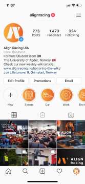
Align Racing’s Instagram (@alignracing) is one of the most important platforms for sharing meaningful moments of implemented work, staying in touch with other teams, attracting new sponsors and maintaining relationships with existing sponsors, team-members, getting new experience and inspiration.
Content
The content of the media posted on AR’s Instagram has to represent a professional level of the organization, its’ development and all kinds of occupations. It can include such posts as:
- Car.
Ludvig, Solan, or any new AR car from all possible angles, its details and parts. Also, AR taking part in various racing events and competitions. - Work in progress.
Moments, where team members are working on their tasks, discussing something, presenting, etc. - Public events.
Pictures and videos taken during the exhibition of AR car in any public space. Team members taking part in various workshops, conferences, meetings related to the development of AR. Events, organized by AR for attracting new team members, sponsors, promoting any specific idea, challenge. Guests, visiting AR workshop and office. - Social events.
Pictures and videos taken during the social events organized for AR members: common trips, parties, gatherings, challenges. - Announcements.
Media that lets people know about any kind of events organized by AR or where AR takes part. Also, recruitment to AR organization or any other invitation to join AR team. - Articles.
Interesting news, press releases, facts, interviews about AR. - Technical.
Posts about new arrivals of the details for the car/car parts, also describing their technical specifications and interesting facts. - Team.
Special achievements of team members, stories or interviews with AR departments, entire team photos, AR clothing. - Creative.
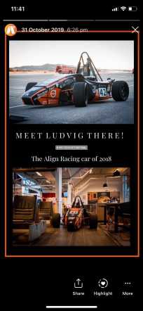
Anything that can represent a nice interesting and engaging idea: it can be any unusual composition on the picture, time-lapses, challenges, any unusual details, regular weekly posts, something fun, something interactive (questionnaires, quizzes in stories) that can engage other teams and followers. - Throwbacks.
This helps when there are not so many new media to be posted. Also, it can be any meaningful moment for AR from the past, from archives. Posts that were published exactly one year ago, or posts about any traditions in AR.
All posts (and further on, posts = picture/video/stories + its written description) should be in English, using the official appropriate language. If there are videos or stories with the original narration in Norwegian, then there should be also a translation to English, e.g. subtitles or in the description. Instagram stories can have both languages (e.g. stories are in Norwegian, but has a short simple title in English). It is important to carefully check grammar before posting.
There are serious regulations for choosing the media content and its description that has to be checked before publishing anything – described in “Media selection” paragraph.
Feed
The gallery of Instagram follows a certain colour palette for a nice first appearance when the new follower opens the gallery. It is not too strict but has to keep consistency and style. Currently, a common preset “2019_ARUiA_General.xmp” is made for editing the pictures and is available on Google Drive. Applying this preset on the pictures helps to keep this consistency.
Instagram is the main platform for communication with other teams, so the posts should also try to invite other followers, other teams
to leave comments under our posts, share, save and repost our media or ask us any questions related to the technical part.
Instagram can show everything about AR, it has both the official posts as on Facebook and, in addition, it has an emphasis on the technical side. So any posts about car technical specifications, parts, etc. are very welcome.
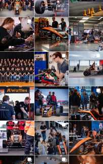
When opening the gallery, the overall look should be balanced as well – an even amount of pictures of AR car, people, car details, videos. It should not be in the way when if you would open the AR profile and see that the last 8 pictures (just an example) are showing the car exhibited in different places, it needs diversity.
Stories
Stories are more suitable for sharing the moments happening in real-time and also letting the viewers know about the newest post in the feed. Stories are also a great tool to maintain the engagement of the followers even if there is nothing to post to the gallery. It is important to use the location and, sometimes, a hashtag sticker in order to attract more viewers, nevertheless, these should not be too noticeable on the story-post itself, they can be placed somewhere in the corner.
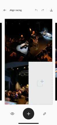
Stories can be also used for publishing collages of different pictures, videos made during the event. If there are too much of media and it cannot be posted all to the feed, then collages are a good solution.

Media selection
What is not allowed to post:
- Posts that can be considered as offensive, discriminative, provocative, consisting of non-trustful information.
- Posts with cursing, rude or impolite expressions, dark humour, sarcasm, any memes.
- Posts with people, who have not given permission to be taken a picture or video of; Kids, whose parents have not given permission to take a picture or video of them and publish them; Drunk or smoking people (this is especially related to any media taken during social or public events).
- Posts of the car which is not officially unveiled yet – anything that can release the new design or unique features. It is important to take care of the pictures taken during design presentations, in the office, workshop – so that the not-unveiled car does not appear on the presentation or PC screens even in the background.
- “Work in progress” posts of technical departments if they are not approved by a technical department leader or HMS leader as “following all safety rules”. Also, any post where team members or other people around the car don’t follow safety rules.
- Posts that are advertising any product not related to the sponsors who have the “Gold Package”.
- Posts that are not related to Align Racing UiA.
- It is important to keep the chronological order of the media taken from different events and prioritize them by importance. For example, if there are new pictures of people working in workshop and pictures from carrier day at UiA – the carrier day pictures should be posted first, even if they were taken one day later because this is a more important event.
Likes
There are some categories of posts that usually get a bit more likes than the others, therefore it is very practical to plan those and publish them regularly:
- Such posts are usually about our female team-members (AR UiA is a big supporter of females in motorsports), e.g. posting pictures of them working, presenting, taking part in public events, having the leading positions etc. It is also important to remember about the 8th of March – International women’s day.
- Posts about socially important cases (e.g. COVID-19), if AR takes part in helping other organizations, supports a certain social position, then it should be captured.
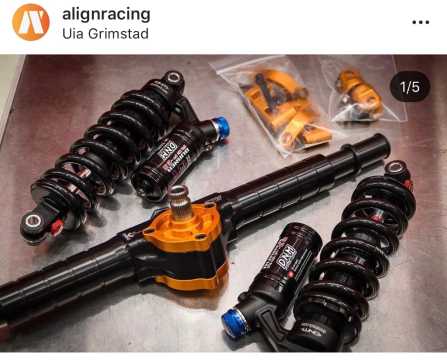
- Since Instagram is chosen to be more about technical things of AR, it works really well posting different descriptions of newly arrived car parts and details. Usually, those become one of the most saved and shared posts.
- Media that shows something dynamic, something moving. It is more attractive for the viewers to see a frozen “moment of the story” / “of an action” in the picture, so the pictures with the car moving or team members working with sparkles flying around – these receive a lot of impressions.
- It is always a good idea to show the whole team doing something together – taking part in competitions, workshops, posing all together with the car.
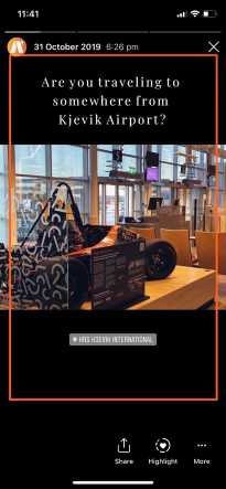
- Posts where AR is somewhere in the recognizable public place, e.g. Ludvig which is exhibited in the Kjevik International Airport – this attracts a lot of likes and impressions too.

Post Frequency
Posts in the feed should be published not oftener than once a day with 24 hours’ difference with the previous publication. Also, it is recommended to wait until the post gets to the barrier of a minimum amount of likes, e.g. minimum 80 likes + 24 hours and then the next post can come.
If there is a need to attract special attention to the post, then it should be posted in the feed and also in the stories. And in the stories, a pause should be taken until the next story. The announcement can be designed in different ways and posted a few times in stories to make people notice something.
Editing
Only media in its’ best quality should be chosen to be posted, pictures and videos with a minimum amount of noise, clear and sharp, not blurred, with a reduced amount of warm white colour that has yellow shades.
For the IGTV videos (videos that are longer than 1 minute), it is recommended to choose, a suitable for the content and for the feed, a vertical picture-cover, or a nice eye-catching moment from the video itself.
AR has a nice contrasting orange colour, so if editing a temperature of the picture in the Instagram editor, it is always better to go for a colder one.
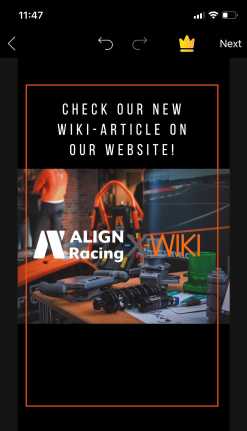
Stories that are posted straight from the location they were taken from, need to have a “Buenos-Aires” filter on and the font called “Modern”. An application that was used for collages (can be checked in the profile’s archive) is called “Unfold”, templates called “CS1” and “CS3” (the last one costs just 11kr), the font –“Playfair”. The application where the frame was made – PicsArt.


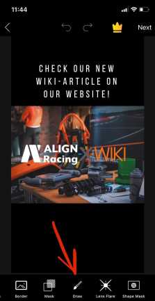
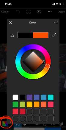
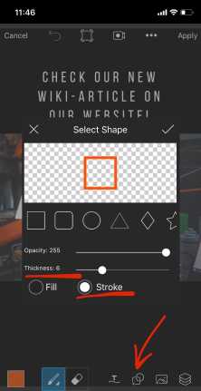
How to make the orange frame in PicsArt:
1. Load the image (finished and saved to the feed collage from Unfold) to the app
2. Open “Draw” (symbol with a brush)
3. Choose the orange colour (the most similar to AR orange recommended)
4. “Select shape” (icon with square, circle and plus)
5. Switch to “Stroke” and choose the thickness 5-10
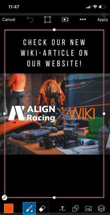
6. Draw the rectangle, adjust its size and place is symmetrically in the middle of the picture so that there is the same distance from each edge to the frame.
Sometimes, media can be also black & white, for this case, it is important to take care of the contrast so that all the elements are clear and recognizable.
Posting one big picture divided into the square-parts, so that when the viewers open the gallery they see one picture (like a puzzle) made of 3-6-9 square pictures. It is a nice and creative idea, but then it is useful to mention under each picture that the viewers should check the whole one in the gallery. In addition, each picture should not look too empty, not understandable – it might lower the number of likes and also affect Instagram’s algorithms.
Insta-Background
The algorithm and structure of Instagram are quite tricky and it still needs to be explored more for developing the best strategy of attracting more of the natural flow of new followers and their engagement.
It is practical to check statistics and insights, try to analyse them and learn the best tendencies. It is always a great idea to keep on exploring profiles of other teams and, especially, professional racing teams and car brands to see the latest trends, to have the option to analyse and compare what looks successful and attractive in the gallery, or what is not so nice.
Followers
The natural flow of new followers requires consistent usage and interaction. It is a big luck to be reposted or tagged by a profile that has a huge audience (e.g. Formula Student), then it attracts a lot of them automatically. It is worth to regularly like and comment on different publications (like all pictures of other teams, do not evaluate it with personal taste). Comments can be simple, even emojis, or, of course, can be questions and compliments – can attract profile visits too.
Mass-liking + following of different profiles works, some of the teams start following back. So the guide is: choosing a team/profile that has a lot of followers themselves and checks who are they following. From the list of profiles, they are following enter different teams – check that they are active (their last post should not be made one year ago), like 10 pictures to be noticed by them, follow them, wait for the response.
Taking part in different challenges and being nominated can also attract new followers.
Besides attracting the new followers, it is also important to take care of interaction with them. Whenever followers ask questions or comment something on stories or posts, they should receive feedback. It might happen that some messages of followers need time to be answered. A good solution for that can be simply choosing a 30-40 minutes a day when replying to all messages in Direct and comments. Those don’t happen every day, but in any case, other profiles should not wait for a response for too long.
Hashtags
Unique hashtags such as “alignracing”, “aruia”, “ar” let find our posts amongst all the other teams. Nevertheless, there are 30 hashtags in total that can be posted under each post.
30 hashtags included in the post’s description look messy and, sometimes, even longer than the title itself. Therefore, a solution can be storing those 30 hashtags in any “Notes” app on the phone, copying them right before making the post and commenting them as fast as possible right under the publication. Pre-copying and posting them as soon as possible in the publication’s comment is needed because hashtags on Instagram update chronologically, so if the hashtag appears one hour later – the publication with this hashtag will be amongst other publications made one hour ago. For instance, some of the hashtags have a big flow – there are a lot of new publications appearing with it every minute, so a belated hashtag under the AR post will get lost under the newest publications.
Here are the hashtags that are used under the media the most:
#alignracing #alignracinguia #team #car #auto #uia #formulastudent #formula #motorsport #design #racing #autosport #teamgoals #sportscar #motorracing #racecar #student #photography #automotive #speed #enginesolidworks #champion #technology #bestofnorway #carlifestyle #supercars #business #racingnorge #teamworkengineering #formulanordic
Of course, all of them can be changed based on the media content and popularity of hashtags.
It works well with Instagram’s algorithms if the hashtags have some diversity under the post, pasting completely the same ones’ every time does not really work.
Hashtags related to a certain challenge, e.g. #12daysofcomp can be included in the post and then 29 other hashtags in the comment.
Hashtags are useful during approximately 24-30 hours after the post has been done – this is the time when the post gets lost under the newest same-hashtag posts and the time when everyone subscribed to a certain hashtag (on Instagram you can follow not only profiles but also different hashtags) has already seen it in their feeds. Therefore, hashtags can be removed after this time, but those that are different from common ones, for instance, “alignracing” should remain.
Following
It is not allowed to follow profiles that are not related to the professional activities of AR, e.g. profiles of personal interest and friends, profiles not related to the automotive industry or at least inspiration for it, e.g. profiles about makeup or gardening. Also, it is not allowed to follow and interact with different bots, profiles that offer likes and followers, suspicious and ghost (empty) profiles.
Once in a while, it is suggested to go through the list of the profiles-following and unfollow those that have stopped their activity, e.g. their last post has been published more than one year ago.
Statistics / Insights
Insights of the profile and its’ subpages “Content”, “Activity”, “Audience” are great tools for analysing and then building a better strategy of Align Racing UiA promotion on social media.


Activity / Audience/ Content
All of them are constantly changing statistics that should be checked regularly, e.g. every week. Basically, Instagram provides a clear and understandable description for each of the statistics in these subpages, however, it is always good to attentively keep track of the tendencies. Posting in the most active time amongst followers is great, but it might be different depending on the situation happening around and be also different every new week. In addition, the most active time of followers cannot always suit the logic of posting a certain category of posts at that time – e.g., posts there might be posts that should be posted in the morning or in the evening but the active time is different.
In general, the analysis of the insights brings more motivation to continue developing the profile and make it really progressing.
Telemetry
Nicolai Ellingsen
Member of electronics department
Managing: Telemetry/Data logging
In order to optimize the performance of a race car, information is essential. By
gathering and analyzing sensor data in real-time, a competitive edge can be gained
for future car designs. This collection and displaying of data is called telemetry.
Wireless Telemetry
Stopping the car to extract data into the telemetry system has been deemed too unrealistic. A wireless solution will also allow for users to monitor the car live during testing and racing therefore increasing its effectiveness. In essence, a fully fledged telemetry system has been chosen over just a simple data logger. A backup will however still be performed by a local storage on the car. The system must be able to provide stable transmission over 600m with a data rate of at least 500 kbit/s.
Wireless Network
Cellular technology mitigates the main issues of prior telemetry systems in Align Racing UiA, namely range. Antenna placement is also no longer an issue since line-of-sight will not
have a great effect, the system can therefore be placed in a more suitable area of the car.
The added running cost of a cellular system is negligible compared to pre-made commercial systems and it also allows for more customization and upgrades in the future.
Some overhead is also needed to ensure that the upload speed is sufficient.
It would also be possible to use LTE-M to decrease latency, but the peak data rate is 384 kbit/s which below the requirements of the system.
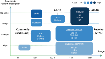
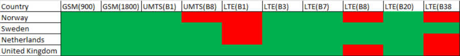
This does however mean that the specific choice of cellular technology must be supported in all countries where Align Racing intends to compete.
Based on this, LTE CAT4 was chosen as it provides ample bandwidth with reasonable latency.
Transport Protocol
Sending data can be done with either HTTP or MQTT in this specific setup. For this use-case, MQTT will offer many advantages. HTTP can do the same things as MQTT, but with a higher footprint (Header size). The system will only send simple telemetry data and MQTT will therefore be more data rate efficient. MQTT is able to establish a connection and keep it open as well. Thus lowering the data rate usage and latency further compared to HTTP.
Hardware
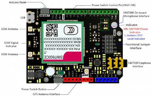
The cellular device chosen for this system is a SIM7600CE-T 4G(LTE) Shield from DFRobot. The operating range of the module is -40◦C and 85◦C. Thereby making it suitable for testing during the Norwegian winters. It features a SIM7600 cellular module and interacts with controlling device using AT Commands sent over a serial interface. This makes it possible to use most microcontroller type devices such as an Arduino to control the device. It was also chosen as Align Racing UiA makes their own CANbus modules that are based on the same microcontroller as an Arduino Nano. A local backup will be used in the car as well using a Teensy and an SD card.
- Operating Voltage: 5V
- Input Power: VIN(7-23V)/USB(5V)
- Supported Networks:
- TDD-LTE B38/B39/B40/B41
- FDD-LTE B1/B3/B8
- TD-SCDMA B34/B39
- WCDMA/HSDPA/HSPA+ B1/B8
- CDMA 1X/EVDO BC0
- GSM/GPRS/EDGE 900/1800 MHz
- 4G Communication Rate:
- Uplink Rate: 50Mbps
- Downlink Rate: 150Mbps
- Controlled via AT Commands
- Supports GNSS (Global Navigation Satellite System)
- Supports Low-power Consumption Mode: 20mA@7V Flight Mode
- Operating Temperature: -40℃~85℃
- Dimension: 69x54mm
Data Analysis Interface
Large amounts of accurate stored or real-time data is near useless if it cannot be accessed in a simple and intuitive way. In order for the largest number of users to be able to benefit from the data, it should be easy to access the specific data they need. It is possible to write data to several text files and read it manually or with a program like excel, but this is far too cumbersome. An interface that allows for simple, accurate and plentiful data to be presented is therefore needed.
Thingsboard
ThingsBoard is a free open-source IoT platform that can be used for data collection, processing and visualization. It has support for MQTT, HTTP and CoAP and can be installed on a user device, server or cloud. Individual users can be given different rights and displays using a login to further increase the ease of use. Data storage is provided either by SQL, NoSQL or a hybrid database. Two types of data is stored; the entities, meaning the devices, users and dashboards, as well as the actual telemetry data using the time as its key. For SQL and NoSQL both databases are combined. The hybrid database separates the two so that the entities are in SQL and telemetry in NoSQL which allows it to capture more than 5000 messages per second. Thingsboard comes with most items needed to display the data, but it is also possible to create them from scratch using JSON code.
User friendliness is one of the most important considerations for this year’s telemetry system. Thingsboard will therefore be used to provide all aspects of the telemetry system outside the car. The ability to display data on devices such as cellphones has also been a reason for this choice since not everyone brings a laptop to test drives. This makes troubleshooting much simpler as anyone can monitor and check the different systems on the car.
Storage
Since the data flow from CANbus is estimated to be much lower than 5000 messages per second, a simple PostgreSQL database will be used. In order to host the thingsboard server, a cloud-based solution will be used. The delay from transmit- ting over a cellular network will already be substantial compared to the difference in hosting a server at Align Racing UiA and a cloud server in Oslo. Using a cloud server also makes storage, backups and up-scaling simpler than running and maintaining hardware at Align Racing UiA, especially with regards to time. Accessing the website is also simplified since thingsboard can be given an external website address. At the moment, the system runs on a cloud server provided by Host1.no. In order to avoid the effects of jitter (packets arriving in the wrong order/ too late) on the telemetry system and to further facilitate the local backup, all data is tied to the car’s gps clock. This means that the local storage can be migrated into the PostgreSQL database with little difficulty.
Upright
Henrik Fidje
Member of suspension department
Managing: In-Wheel
The upright assembly has many functions within the wheel assembly. It houses the wheel hub, which allows for connection and rotation of the wheels. The brake calipers are mounted to the upright. Steering mounts allows for steering of the wheels in the front and toe control in the rear. It also connects the double wishbones to the outboard assembly and transfers the forces from the tire contact patch to the suspension links. In addition to all these functions, which allow for safe and functional handling of the car, there are also some structural conditions that are important to take into account when designing an upright.
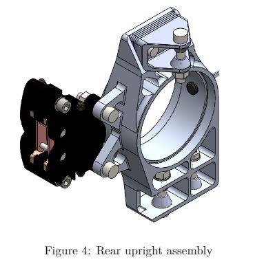
The suspension system is not a static system, as everything is elastic to some extent (compliance). There are large forces that are transferred through many components in the inwheel assembly. These forces will cause compliance which will affect the chosen suspension geometry and, in most cases, reduce handling. Figure 3 and Figure 4 shows both the front and rear upright assembly.
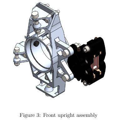
Front upright assembly
One of the main focuses for this year compared to last year is to reduce weight, generate better load paths and improve the workability of the attached components. In addition to this, a wheel speed concept, that was partially integrated last year, has been fully implemented to the upright assembly.
Adjustability has also been an important factor in the 2020 design. Because of some unseen challenges, many variables in the suspension geometry has not been sufficiently simulated. Therefore, adjustability has been important to ensure that during the test phase of the vehicle the best possible camber and steering geometry can be found. This will also provide valuable data for teams in the future, as fewer changes will be made in the suspension.
To adjust the camber angle, shims with variable thicknesses are mounted with the upper wishbone bracket, as shown in \Figure 3. This allows us to adjust the camber angle up to 3.5 degrees. In the front tie-rod attachment, a double shear clevis attachment is mounted. The reason for this clevis attachment is the possibility for adjustment if the steering geometry is not adequate. From simulations and calculations, there will most likely not be any problems. In addition, this will allow for a much simpler machining job, as it can be done quite simply with a 3-axis CNC mill.
All spacers are made conical to both reduce the pressure acting on the upright and brackets and allow for more radial rotation of the uniball bearings.
Cuts in the lower wishbone mount have also been made, to ensure that the wishbones do not touch the upright under operation. In the previous years, this was honed manually, which was a time-consuming task.
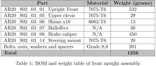
Table 1 shows a BOM and weight table for the front upright assembly. From last year, the front hub size has decreased significantly, which has made it possible to reduce the weight of the front upright by 21 %. Comparing last years upright with the current design, there has been a significant increase in stiffness. This is due to better load paths and a better understanding of where the critical areas are.
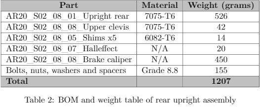
Rear upright assembly
The same focus has been made under the construction of the rear upright, as with the front upright. The size of the bore of the upright is the same as last year, to accommodate for the in-hub tripod joint, which has shown to be a very successful concept. One other major change is the tie-rod attachment. Last year the team tried to use bumpsteer to their advantage and allow for some rear-wheel steering. This concept was proved not to be successful. For the 2020 season, the team tried to reduce bumpsteer in the rear to a minimum, as rear toe-control is far more important.
To reduce the rear bumpsteer, the tie-rod attachment is in-plane with the lower wishbone attachment. The tie-rod attachment on the rear bulkhead is also attached at the same point. This will, in theory, result in no bumpsteer at all.
There has also been a focus on camber adjustment in the rear with shims. These shims will also have a variable thickness so that the team can evaluate the best camber settings for competition.
Table 2 shows a BOM and weight table of the rear upright assembly. The weight of the upright has improved by about 20 % from last year, even though the bore size of the hub has stayed the same. There has also been a significant improvement in the compliance in the rear tie-rod attachment.
Rules
Relevant rules for the inwheel assembly:
- T 2.3.1 – The vehicle must be equipped with fully operational front and rear suspension systems including shock absorbers and a usable wheel travel of at least 50 mm and a minimum jounce of 25 mm with driver seated.
- T 2.4.1 – Any wheel mounting system that uses a single retaining nut must incorporate a device to prevent loosening of the nut and the wheel. A second nut (“jam nut”) does not meet these requirements.
- T 2.4.2 Standard wheel lug bolts and studs must be made of steel and are considered engineering fasteners. Teams using modified lug bolts, studs or custom designs will be required to provide proof that good engineering practices have been followed in their design. Wheel lug bolts and studs must not be hollow.
- T 2.4.3 – Aluminum wheel nuts may be used, but they must be hard anodized and in pristine condition.
- T 2.6.3 – The steering system must have positive steering stops that prevent the steering linkages from locking up. The stops must be placed on the rack and must prevent the tires and rims from contacting any other parts. Steering actuation must be possible during standstill.
- T 10.1.1 – Critical fasteners are defined as bolts, nuts, and other fasteners utilized in the primary structure, the steering, braking, driver’s harness, suspension systems and those specifically designated as critical fasteners in the respective rule.
- T 10.1.2 – All threaded critical fasteners must be at least of either 4 mm in diameter or of the diameter specified in the referencing rule, whichever is larger.
- T 10.1.3 – All threaded critical fasteners must meet or exceed metric grade 8.8 or equivalent.
- T 10.1.4 – All threaded critical fasteners must be of the type hexagon bolts (ISO 4017, ISO 4014) or socket head cap screws (ISO 4762, DIN 7984, ISO 7379) including their fine-pitch thread versions. Alternative fasteners are permitted if the team can show equivalence.
- T 10.1.5 – Bolts may be shortened in length as long as T 10.2.3 is fulfilled.
- T 10.2.1 – All critical fasteners must be secured from unintentional loosening by the use of positive locking mechanisms.
- T 10.2.2 The following methods are accepted as positive locking mechanisms:
- Correctly installed safety wiring.
- Cotter pins.
- Nylon lock nuts (ISO 7040, ISO 10512, EN 1663 or equivalent) for low temperature locations (80 ◦C or less).
- Prevailing torque lock nuts (DIN 980, ISO 7042 or equivalent, and jet nuts or K-nuts).
- Locking plates.
- Tab washers.
- Any locking mechanism based on pre-tensioning or an adhesive is not considered a positive locking mechanism.
- T 10.2.3 – A minimum of two full threads must project from any lock nut.
- T 10.2.4 – All spherical rod ends and spherical bearings on the steering or suspension must be in double shear or captured by having a screw/bolt head or washer with an outer diameter that is larger than the spherical bearing housing inner diameter.